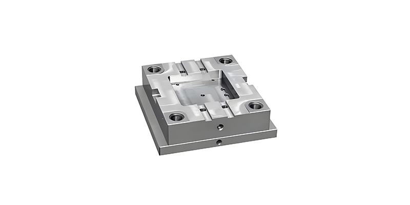
Tolerances and Fits in Injection Molding
A comprehensive guide to achieving precision in precision injection molding through proper tolerance management and fit selection.
Table of ContentsTable of Contents
-
Tolerances and Fits for Common Parts in Injection Mold Assembly Drawings
-
Injection Mold Cavity Dimension Tolerances
-
Injection Mold Fit Dimension Tolerances
-
Mold Base Tolerances and Surface Roughness Requirements
-
Common Form and Position Tolerances for Injection Mold Parts
-
Surface Roughness of Mold Components
-
Selection of Surface Roughness Values
-
Other Requirements
1 Tolerances and Fits for Common Parts in Injection Mold Assembly Drawings
In precision injection molding, understanding the tolerances and fits for common parts in injection mold assembly drawings is fundamental to ensuring mold functionality, part quality, and production efficiency—especially for the injection molding parts (the final components produced by the mold) that rely on these tolerances for dimensional accuracy. These tolerances define the permissible variation in dimensions between mating components: they not only ensure the mold itself assembles smoothly but also directly determine whether injection molding parts can fit with other components in end products (e.g., a plastic gear as an injection molding part matching a metal shaft) and maintain consistent performance during use.
The selection of appropriate tolerances depends on several factors including the material being molded, part complexity, production volume, and functional requirements. For precision injection molding applications, tighter tolerances are typically required to ensure consistent part quality and proper assembly.
Common fitting types in injection mold assemblies include clearance fits, interference fits, and transition fits. Clearance fits allow for intentional space between components, facilitating movement or disassembly. Interference fits create a permanent or semi-permanent connection through controlled dimensional overlap. Transition fits fall between these two extremes, allowing either clearance or interference depending on manufacturing variations.
For guide pillars and bushings, a typical clearance fit might specify H7/f6, where the hole (H7) has a basic size with an upper tolerance, and the shaft (f6) has a basic size with a lower tolerance. This ensures smooth movement while maintaining alignment.
Ejector pins commonly use H8/f7 fits to ensure proper functioning while minimizing flash. Core and cavity inserts often require tighter fits such as H7/m6 to prevent plastic leakage while allowing for thermal expansion during the molding process.
In precision injection molding applications where tight dimensional control is critical, these tolerances may be tightened further, sometimes requiring specialized manufacturing processes to achieve the necessary precision.
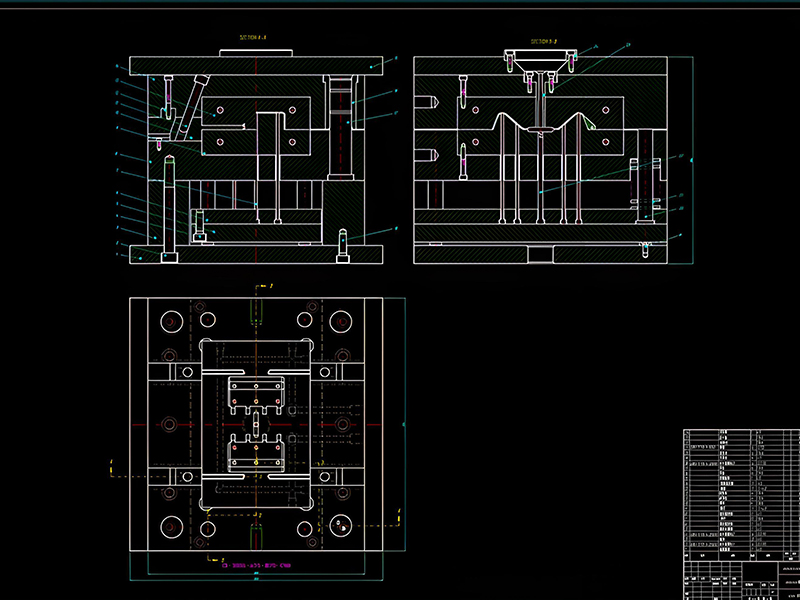
Common Tolerance Classes for Mold Components
| Component | Fit Type | Tolerance Class |
|---|---|---|
| Guide Pillars/Bushings | Clearance | H7/f6 |
| Ejector Pins | Clearance | H8/f7 |
| Core Inserts | Transition | H7/m6 |
| Cavity Inserts | Transition | H7/k6 |
| Leader Pins | Clearance | H7/g6 |
Table 1: Typical tolerance classes for common injection mold components used in https://quantamnhadat.com/wp-content/uploads/2025/08/precision-injection-molding.jpg
2 Injection Mold Cavity Dimension Tolerances
The primary goal of refining injection mold cavity dimension tolerances is to ensure the accuracy of injection molded parts—a priority that makes these tolerances critical factors in determining the final dimensions of molded components. These tolerances must account for both the mold manufacturing variations (which can introduce small errors into cavity size) and the material shrinkage that occurs during the cooling process in precision injection molding: this dual consideration ensures that even after the plastic cools and shrinks, the resulting injection molded parts still align with the required dimensional standards.Optical Transceiver.
The cavity dimensions are typically calculated by accounting for the part's nominal dimensions plus a shrinkage allowance specific to the plastic material being used. Common shrinkage values range from 0.5% to 2.5% for most thermoplastics, though some engineering resins may have different shrinkage characteristics.
For precision injection molding applications, cavity tolerances are generally specified as ±0.01mm to ±0.05mm for small dimensions, with larger dimensions allowing slightly more variation (typically ±0.05% to ±0.1% of the nominal size). These tight tolerances ensure that even after accounting for material shrinkage, the final part dimensions remain within the specified range.
When specifying cavity tolerances, it's important to consider the part's functional requirements. Critical dimensions that affect assembly or performance should be given tighter tolerances than non-critical features. This selective application of tight tolerances helps balance part quality with manufacturing costs.
The method of cavity machining also influences achievable tolerances. Processes like CNC milling can typically hold tolerances of ±0.01mm, while EDM (Electrical Discharge Machining) can achieve even tighter tolerances of ±0.005mm or better, making it suitable for precision injection molding applications.
Additionally, cavity tolerances must account for thermal expansion of the mold during the molding process. The mold material (typically tool steel) expands when heated, which can affect cavity dimensions. This thermal effect is more pronounced in high-temperature molding processes and must be considered when specifying final cavity tolerances.
Cavity Tolerance Guidelines by Material
Chart 1: Typical cavity tolerance ranges for different materials used in precision injection molding
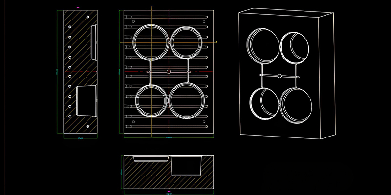
Shrinkage Allowance Factors
- Account for material-specific shrinkage when calculating cavity dimensions
- Consider directional shrinkage for materials like ABS and polypropylene
- Include additional allowance for parts with thick cross-sections
- Adjust for processing parameters in precision injection molding that may affect shrinkage
3 Injection Mold Fit Dimension Tolerances
Injection mold fit dimension tolerances define the permissible variation between mating components in an injection mold, ensuring proper alignment, function, and prevention of plastic leakage. These tolerances are critical in precision injection molding where even minor misalignments can cause part defects or mold damage.
The most common fit types specified in injection molds include clearance fits, transition fits, and interference fits, each serving different purposes for the injection molded part. Clearance fits allow movement between components, transition fits provide either clearance or interference depending on manufacturing variations, and interference fits create a permanent bond between components.
For guiding components such as leader pins and bushings, a running or sliding fit (H7/g6 or H7/f7) is typically specified to ensure smooth movement while maintaining alignment. These fits provide minimal clearance to prevent lateral movement that could affect part dimensions in precision injection molding applications.
When two components must be precisely located without movement, a transition fit such as H7/k6 or H7/m6 is commonly used. This type of fit is typical for core and cavity inserts, ensuring they remain securely in place while allowing for thermal expansion during molding cycles.
Interference fits (e.g., H7/p6 or H7/s6) are used for components that must be permanently assembled, such as ejector retainer plates and guide bushings pressed into the mold plates. These fits require controlled force during assembly and create a strong, permanent connection.
In precision injection molding, the selection of fit tolerances must also consider the effects of thermal expansion during molding. Mold components can reach temperatures of 50°C to 150°C (122°F to 302°F) during operation, causing dimensional changes that must be accounted for in the tolerance specifications.
The choice of fit tolerance directly impacts mold manufacturing costs. Tighter tolerances require more precise machining processes and greater inspection efforts, increasing production costs. Therefore, it's essential to specify the loosest possible tolerances that still meet injection parts' functional requirements to optimize manufacturing efficiency.
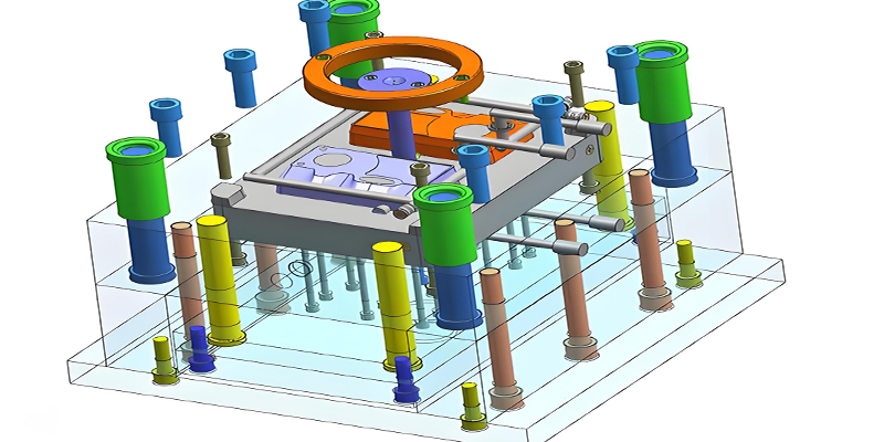
Fit Tolerance Classifications
Clearance Fits
Allow movement between components with intentional space
- H7/g6: Small clearance for sliding fits
- H7/f7: Medium clearance for running fits
- H8/e8: Larger clearance for loose fits
Transition Fits
May provide clearance or interference depending on variation
- H7/k6: Slight clearance or minimal interference
- H7/m6: More likely to have interference
Interference Fits
Create permanent assembly through controlled interference
- H7/p6: Light press fit
- H7/s6: Medium press fit
- H7/u6: Heavy press fit
These classifications are essential in precision injection molding to ensure proper component interaction.
4 Mold Base Tolerances and Surface Roughness Requirements
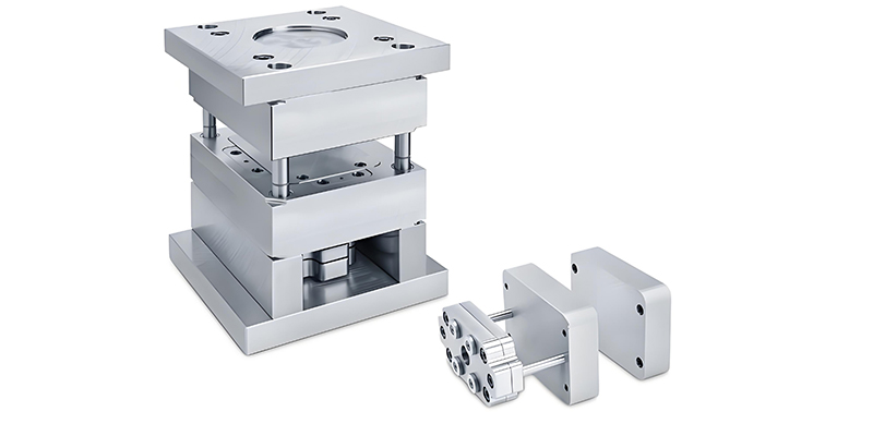
The mold base tolerances and surface roughness requirements form the foundation of any injection mold, a core part of tooling for injection moulding, providing the structural framework that supports the cavity and core inserts, guide components, and other critical elements. In precision injection molding, the mold base must maintain dimensional stability under the thermal and mechanical stresses of repeated molding cycles.
Mold base plate thickness tolerances typically range from ±0.1mm to ±0.2mm for standard applications, with tighter tolerances of ±0.05mm available for precision injection molding requirements. The parallelism of mold plates is equally important, generally specified as 0.05mm per 1000mm of length to ensure proper alignment during mold closing.
Hole positioning tolerances in mold base plates are critical for proper component alignment, essential for plastic injection molding parts. For guide pillar and bushing holes, positional tolerances of ±0.02mm to ±0.05mm are common, ensuring that the moving half of the mold aligns precisely with the stationary half during each molding cycle.
Surface flatness requirements for mold plates typically range from 0.03mm to 0.1mm per 1000mm, depending on plate size and application. This flatness ensures uniform clamping pressure distribution across the mold, preventing flash and ensuring consistent part quality.
Surface roughness requirements for mold base components vary by function. Non-cosmetic surfaces typically have a roughness value (Ra) of 1.6μm to 3.2μm, achieved through standard milling and grinding processes. Surfaces that mate with other components may require finer finishes of 0.8μm Ra, while critical guiding surfaces might need 0.4μm Ra or better to ensure smooth movement and minimize wear.
In precision injection molding applications, mold base materials must also be carefully selected to maintain dimensional stability under operating conditions. Pre-hardened steels like S50C or 45# steel are common for standard mold bases, while higher-grade steels such as P20 or 718H may be specified for more demanding applications requiring greater wear resistance and stability.
Proper heat treatment of mold base components is essential to achieve the required hardness and dimensional stability. Typical hardness ranges from 28 to 32 HRC for pre-hardened steels, providing a balance of machinability and wear resistance suitable for most precision injection molding applications.
Mold Base Tolerance Specifications
| Feature | Standard Tolerance | Precision Tolerance |
|---|---|---|
| Plate Thickness | ±0.1mm to ±0.2mm | ±0.05mm |
| Parallelism | 0.1mm/1000mm | 0.05mm/1000mm |
| Hole Position | ±0.05mm | ±0.02mm |
| Flatness | 0.1mm/1000mm | 0.03mm/1000mm |
Surface Roughness Requirements
Chart 2: Surface roughness requirements for different mold base components in precision injection molding
5 Common Form and Position Tolerances for Injection Mold Parts
Common form and position tolerances for injection mold parts are essential for ensuring proper functionality, alignment, and interchangeability of components. These geometric tolerances control the shape, orientation, and location of features beyond what can be achieved with simple dimensional tolerances, making them particularly important in precision injection molding.
Form tolerances control the shape of individual features without reference to other features. The most common form tolerances used in parts injection mold components include straightness, flatness, circularity, and cylindricity. For guide pillars, a straightness tolerance of 0.01mm per 100mm length ensures proper alignment with bushings during mold operation.
Flatness tolerances are critical for mold plate surfaces that mate together, typically specified as 0.05mm per 1000mm to ensure uniform clamping pressure distribution. In precision injection molding applications, this may be tightened to 0.03mm per 1000mm for critical surfaces.
Position tolerances control the location of features relative to datums or other features. For example, in mold injection manufacturing, the positional tolerance between guide pin holes in the stationary and moving mold plates is typically specified as φ0.02mm at maximum material condition (MMC), ensuring proper alignment during mold closing.
Perpendicularity tolerances are important for features like mold cavities that must be perfectly aligned with the mold opening direction. A typical perpendicularity tolerance of 0.02mm per 100mm ensures that cavity surfaces are square to the parting line, preventing uneven wall thickness in the molded part.
Parallelism tolerances control the orientation of two surfaces relative to each other. For example, the parallelism between the ejector plate and the mold cavity plate is often specified as 0.03mm per 100mm to ensure uniform ejection of parts in precision injection molding processes.Electronic shelf labels.
Runout tolerances are used to control the concentricity of rotating or mating cylindrical features. For example, the total runout of an ejector pin relative to its guide bushing may be specified as 0.01mm, ensuring smooth operation without binding.Related Hydraulic Spare Parts.
When applying geometric tolerances, it's important to establish appropriate datums that represent the functional references of the part. For mold components, datums typically include the parting line surface, guide pin holes, and other critical locating features that ensure proper assembly and function in precision injection molding applications.
