Precision Hot Runner Injection Mold Design
The definitive guide to mastering hot runner systems for optimal plastic molding performance, efficiency, and quality.
Hot runner systems represent the pinnacle of modern injection mold technology, offering superior control, efficiency, and quality in plastic molding processes. This comprehensive guide outlines the critical steps and considerations in hot runner injection mold design, providing engineering professionals with the knowledge needed to optimize their plastic molding operations.
From initial design steps through to final component selection and real-world applications, each phase of hot runner system development is explored in detail, ensuring that your plastic molding projects achieve maximum performance and cost-effectiveness.
Hot Runner Design Steps
The development of an effective hot runner system begins with a systematic approach to design, ensuring that all aspects of the plastic molding process are considered. Proper design sequencing prevents costly errors and ensures optimal performance.
The first phase involves comprehensive product analysis, where the part geometry, material properties, and production requirements are evaluated. This analysis forms the foundation for all subsequent design decisions in the plastic molding process.
Following product analysis, designers must determine the optimal gate locations. Gate placement directly impacts part quality, material flow, and cycle time in plastic molding operations. Computer-aided engineering (CAE) tools are invaluable at this stage for simulating flow patterns.
Next, the overall hot runner system layout is developed, including manifold configuration, nozzle selection, and heater placement. This step requires balancing thermal uniformity with mechanical efficiency to ensure consistent plastic molding results.
Thermal analysis is then performed to verify temperature distribution across the system, preventing cold spots that could compromise plastic molding quality. Computational fluid dynamics (CFD) simulations help optimize cooling channel placement relative to heating elements.
The final design step involves integrating the hot runner system with the mold base, ensuring proper alignment, support, and connection to the injection molding machine. This integration phase is critical for maintaining system integrity during high-pressure plastic molding cycles.
Hot Runner Design Workflow
A systematic approach ensures optimal performance in plastic molding applications. Each step builds upon the previous to create a cohesive system.
Hot Nozzle Design
The hot nozzle is a critical component in any hot runner system, serving as the interface between the manifold and the mold cavity. Its design directly influences material flow, pressure distribution, and heat control in plastic molding processes.
Nozzle tip geometry is carefully engineered to match the gate size and part requirements. The tip must provide a smooth transition for the molten plastic, minimizing shear stress and ensuring consistent filling in plastic molding operations.
Heater design is another crucial aspect of hot nozzle engineering. Cartridge heaters, band heaters, or etched foil heaters may be employed, depending on the required temperature range and uniformity. Proper heater placement prevents cold spots that could disrupt plastic molding flow.
Thermal insulation between the hot nozzle and the cold mold is essential to maintain temperature stability and reduce energy consumption. Insulators made from high-temperature plastics or ceramics create a thermal barrier while allowing for proper alignment.
Nozzle body materials must withstand high temperatures, pressure, and chemical exposure from molten resins. H13 tool steel is commonly used for its excellent combination of heat resistance and toughness in demanding plastic molding environments.
For applications requiring precise gate control, valve-gated nozzles incorporate a mechanical pin that opens and closes the gate. This design offers advantages in controlling gate vestige and managing material flow in complex plastic molding scenarios.
Anatomical View of Hot Nozzle
Precision-engineered components work together to maintain optimal temperature and flow characteristics in plastic molding applications.
Hot Runner Manifold Design
The hot runner manifold serves as the distribution center of the system, channeling molten plastic from the injection unit to each nozzle. Its design requires careful consideration of flow balance, thermal management, and mechanical integrity in plastic molding systems.
Manifold flow channels are precision-machined to ensure balanced flow to all cavities. Computational flow analysis is used to optimize channel diameter, length, and geometry, ensuring equal fill times and pressures across all mold cavities in multi-cavity plastic molding tools.
Thermal uniformity is critical in manifold design. Heater elements are strategically placed to maintain consistent temperatures throughout the manifold, preventing material degradation or premature solidification in plastic molding processes.
Manifold material selection depends on the operating temperature and the materials being processed. P20 and H13 steels are commonly used for general plastic molding applications, while stainless steel may be required for corrosive materials or medical applications.
The manifold must also be designed to accommodate thermal expansion. Proper mounting systems allow for controlled movement while maintaining alignment with nozzles and the injection machine, preventing leaks in high-pressure plastic molding operations.
Modern manifold designs often incorporate modular components, allowing for easier maintenance and reconfiguration. This modular approach facilitates quicker changeovers and reduces downtime in plastic molding production environments.
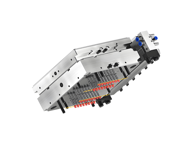
Hot Runner Manifold Configuration
Computer-aided design ensures optimal flow distribution and thermal management for consistent plastic molding results.
Wiring Duct Design
Proper wiring duct design is essential for the safe and reliable operation of hot runner systems. These channels house the electrical components that control heating elements and sensors, playing a critical role in maintaining process stability in plastic molding operations.
Wiring ducts must provide adequate space for all electrical components while ensuring proper separation of power and signal lines. This separation minimizes electromagnetic interference that could disrupt temperature control in sensitive plastic molding applications.
The duct layout should facilitate easy access for maintenance and troubleshooting. Clear labeling and logical organization of wires reduce downtime when service is required, keeping plastic molding production on schedule.
Materials used for wiring ducts must withstand the high-temperature environment of hot runner systems. Heat-resistant polymers or metal channels with insulation are commonly employed to protect wires from thermal damage in plastic molding equipment.
Strain relief is another important consideration in duct design. Proper securing of wires at entry and exit points prevents fatigue and breakage from thermal cycling and vibration during plastic molding operations.
Modern designs often incorporate modular duct systems that can be easily modified or expanded. This flexibility allows for design changes or upgrades without major rework, adapting to evolving plastic molding requirements.
Finally, wiring ducts must be designed to prevent the ingress of contaminants such as plastic particles or cooling water. Sealed designs with appropriate gaskets maintain electrical integrity and prevent shorts in critical plastic molding equipment.
Optimized Wiring Duct System
Well-designed wiring channels ensure reliable electrical performance and simplify maintenance in plastic molding equipment.
Hot Nozzle Thermal Expansion Calculation
Thermal expansion is a critical factor in hot nozzle design, as temperature variations during plastic molding operations cause dimensional changes that must be accounted for to maintain system integrity and performance.
The calculation of thermal expansion begins with determining the operating temperature range of the nozzle, which is influenced by the plastic material being processed and the specific plastic molding requirements. Different polymers require different processing temperatures, affecting expansion rates.
The coefficient of thermal expansion (CTE) of the nozzle material is a key parameter in these calculations. For example, H13 tool steel has a CTE of approximately 11.5 × 10^-6 per °C, meaning precise calculations are necessary for proper plastic molding system design.
Engineers use the formula ΔL = L₀ × α × ΔT, where ΔL is the change in length, L₀ is the original length, α is the CTE, and ΔT is the temperature change. This calculation ensures proper clearance between components during both startup and operating conditions in plastic molding.
Radial expansion must also be considered to prevent binding or excessive clearance in nozzle assemblies. This is particularly important for valve-gated systems where precise movement of the valve pin is essential for proper plastic molding gate control.
Thermal expansion calculations are integrated into the design of mounting systems, allowing for controlled movement while maintaining alignment. This prevents excessive stress on components during thermal cycling in plastic molding operations.
Finite element analysis (FEA) is often employed to simulate thermal expansion under various operating conditions, ensuring that all potential scenarios are accounted for in the final design. This advanced analysis helps optimize plastic molding system performance and reliability.
Thermal Expansion Calculation Example
Temperature vs. expansion curve for common hot runner materials used in plastic molding applications.
Hot Nozzle Selection
Selecting the appropriate hot nozzle is a critical decision in hot runner system design, as it directly impacts part quality, cycle time, and overall plastic molding performance. The selection process must consider multiple factors specific to each application.
Plastic material properties are primary considerations in nozzle selection. High-temperature materials like PEEK require nozzles capable of maintaining elevated temperatures, while shear-sensitive materials may need specialized tip designs to prevent degradation during plastic molding.
Part geometry influences both nozzle type and gate location. Small, intricate parts may require mini nozzles with precise gate control, while large parts might benefit from multiple nozzles to ensure proper filling in plastic molding operations.
Production volume is another key factor. High-volume plastic molding applications typically benefit from more robust nozzle designs with features like replaceable tips to minimize downtime during maintenance.
Gate type selection is integral to nozzle choice. Edge gates, submarine gates, fan gates, and valve gates each offer distinct advantages depending on the part requirements. Valve gates provide superior control over gate vestige, making them ideal for cosmetic plastic molding applications.
Nozzle size and capacity must match the material flow requirements of the application. Undersized nozzles can cause excessive pressure drop and shear, while oversized nozzles may lead to longer cycle times in plastic molding processes.
Compatibility with existing equipment is also a practical consideration. The selected nozzles must integrate properly with the mold base, injection machine, and control system to ensure seamless operation in plastic molding production.
Finally, cost considerations must be balanced against performance requirements. While high-performance nozzles may have a higher initial cost, they can provide significant savings in long-term plastic molding production through improved efficiency and reduced scrap.
Hot Nozzle Types Comparison
Different nozzle designs offer unique advantages for specific plastic molding requirements and material characteristics.
Hot Runner Injection Mold Design Examples
Examining real-world hot runner system implementations provides valuable insights into successful design principles and practical solutions for common plastic molding challenges. These examples demonstrate the application of design concepts in diverse manufacturing scenarios.
In automotive plastic molding applications, a multi-cavity hot runner system for producing dashboard components utilizes sequential valve gating to control flow into different sections of the part. This approach minimizes warpage and ensures consistent wall thickness in large, complex components.
Medical device manufacturing employs hot runner systems with specialized nozzles designed for cleanroom environments. These systems feature stainless steel construction, minimal dead spots, and enhanced temperature control to meet the stringent requirements of medical plastic molding applications.
Packaging industry examples showcase hot runner designs optimized for high-volume production. Stack molds with hot runners double output without increasing floor space, while specialized nozzle tips create precise seal surfaces critical for container functionality in plastic molding operations.
Electronics manufacturing utilizes micro hot runner systems for producing small, intricate components with tight tolerances. These systems feature miniaturized nozzles and precise temperature control to handle the specialized engineering resins used in electronic plastic molding applications.
Large-part plastic molding, such as automotive bumpers, demonstrates the use of multiple hot nozzles strategically placed to ensure proper filling of large cavities. These systems often incorporate sequential valve gating to manage flow front advancement and minimize internal stresses.
Multi-material plastic molding examples illustrate hot runner systems designed to process different materials sequentially or simultaneously. These complex systems require precise timing and temperature control to bond dissimilar materials successfully in applications ranging from consumer goods to industrial components.
Each of these examples highlights the importance of tailoring hot runner design to specific plastic molding requirements, material characteristics, and production goals, emphasizing the customized nature of effective hot runner system implementation.
Automotive Application
Multi-cavity system for interior components
Medical Application
Cleanroom-compatible hot runner design
Packaging Application
High-volume stack mold system
Electronics Application
Micro hot runner technology
Achieving Excellence in Hot Runner Design
The successful implementation of hot runner systems in plastic molding requires a comprehensive understanding of each design phase, from initial concept through to final component selection and system integration. By following the systematic approach outlined in this guide, engineers can optimize hot runner performance for their specific plastic molding applications.
Continuous advancements in materials, heating technology, and control systems are expanding the capabilities of hot runner systems, enabling more complex plastic molding applications with higher precision and efficiency. Staying informed about these developments ensures that your hot runner designs remain at the forefront of technology, delivering maximum value in plastic molding production environments.