Types and Basic Requirements of Mould Design Drawings
A comprehensive guide to the essential drawings in professional mould design and their specifications
In professional mould design, engineers must efficiently produce various technical drawings to shorten production cycles and ensure manufacturing accuracy. These drawings form the foundation of successful mould production, guiding every stage from initial concept to final assembly. This detailed guide outlines the key types of drawings used in mould design and their specific requirements.
The following sections describe the essential drawings required for comprehensive mould design, each serving a specific purpose in the development and manufacturing process. Understanding these documents is crucial for anyone involved in mould design and production.
Essential Drawings in Mould Design
To streamline the mould production cycle, design personnel must promptly provide the following drawings:
- Mould Structure Sketch
- Plastic Part Drawing
- Cavity Layout Drawing
- Mould Base Drawing
- Moving and Fixed Mould Part Sketches
- Mould Assembly Drawing
- Component Drawings
- Wire EDM Drawings
- Ejector Pin Layout Drawing
- Electrode Drawings
- 3D Model Drawings
Mould Structure Sketch
Purpose
Used for ordering mould bases, moving and fixed mould inserts, and frame opening. This fundamental document in mould design guides the initial manufacturing steps.
Content
Includes moving mould sketch + main cross-sections, with annotations for mould base specifications, frame opening dimensions, moving and fixed mould dimensions, plastic part layout/parting/feeding positions.
Drawing Steps
- Determine the gating system: Based on plastic part shape, size, and quantity, select two-plate or three-plate mould base.
- Choose parting surface: Priority to flat surfaces, then inclined surfaces, finally curved surfaces; when parting line affects appearance, customer approval is required, and need to determine if plastic part will stick to fixed mould during mould opening.
- Determine insert positions: Weak, difficult-to-machine, or poorly vented structures should be assembled from separate pieces.
- Plan ejection method: Determine if side core pulling or forced ejection is needed; if using ejector pins/ejector sleeves, determine their positions, sizes, and quantities (while considering cooling channels to avoid interference).
- Arrange cooling channels: Priority to place at cavity bottom/side, passing through heat concentration areas; when water flow is impossible, add cooling pins or use beryllium copper inserts.
- Determine insert dimensions and steel materials: Insert dimensions should be rounded, thickness standardized; steel selection based on plastic type, part transparency, precision requirements, and production volume in mould design.
- Select mould base specifications: Determine mould base size based on feeding method, inner mould insert size, hot runner/double ejector plate/side core pulling mechanism.
Plastic Part Drawing
The plastic part drawing involves revising the customer's part design (considering draft angles, tolerance fits), inputting into computer systems, and filing according to company standards with proper numbering. This step is crucial in mould design as it forms the basis for all subsequent mould components.
The revised drawing must accurately reflect the final part dimensions after accounting for material shrinkage, which is a critical consideration in mould design. Proper draft angles ensure easy ejection from the mould, reducing production issues and improving part quality.
Tolerances must be carefully specified based on functional requirements, with special attention to mating surfaces. This document serves as the reference point for all cavity and core dimensions in the mould design process.
Cavity Layout Drawing
Application Scenarios
Used for complex moulds where manual drawing is difficult, created by designers according to supervisor instructions. This specialized document in mould design helps visualize how multiple cavities will be arranged.
Content
Includes moving and fixed mould layouts + side views, with complete side core pulling structures if applicable; shows layout, pillow positions, and feeding; can include plastic part layout or approximate outlines.
The cavity layout is a critical aspect of mould design that affects production efficiency, part quality, and mould complexity. Proper layout ensures balanced filling of all cavities, uniform cooling, and ease of manufacturing.
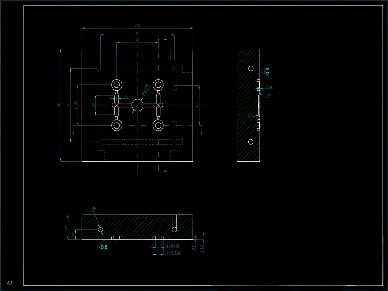
Mould Base Drawing
Application Scenarios
Created for non-standard mould bases or when frame processing is required. Standard mould bases may omit some dimensions.
Requirements
Clearly express processing dimensions on A4 paper; standard mould bases may omit some dimensions. Precision in these dimensions is vital for successful mould design and assembly.
Content
- Templates (fixed mould, moving mould, square iron, etc.)
- Guide pillars/bushings and screws, locating pins
- Ejector plate guide pillars/bushings, return pins
- Ejector plate limit pins/screws, prying slots
- Venting grooves, lifting screw holes/clamping slots
- Inserts/sliders/wedge blocks, etc.
- Dimensions (coordinates, plate thickness, part parameters, tolerances)
- Template steel grades (see Figure 1-34)
The mould base drawing forms the foundation structure in mould design, determining the overall size and stability of the mould during operation.
Moving and Fixed Mould Part Sketches
Purpose
Issued to the workshop for material preparation, reference surface grinding, screw hole drilling, and frame matching when the assembly drawing is not yet completed. These sketches accelerate the manufacturing process in mould design.
Requirements
Only major dimensions need to be标注. These sketches focus on critical measurements necessary for initial processing steps, allowing production to begin while detailed mould design work continues.
The sketches should clearly indicate reference datums, critical surfaces, and any special processing requirements. While less detailed than final drawings, they must accurately represent the essential features needed for manufacturing planning in mould design.
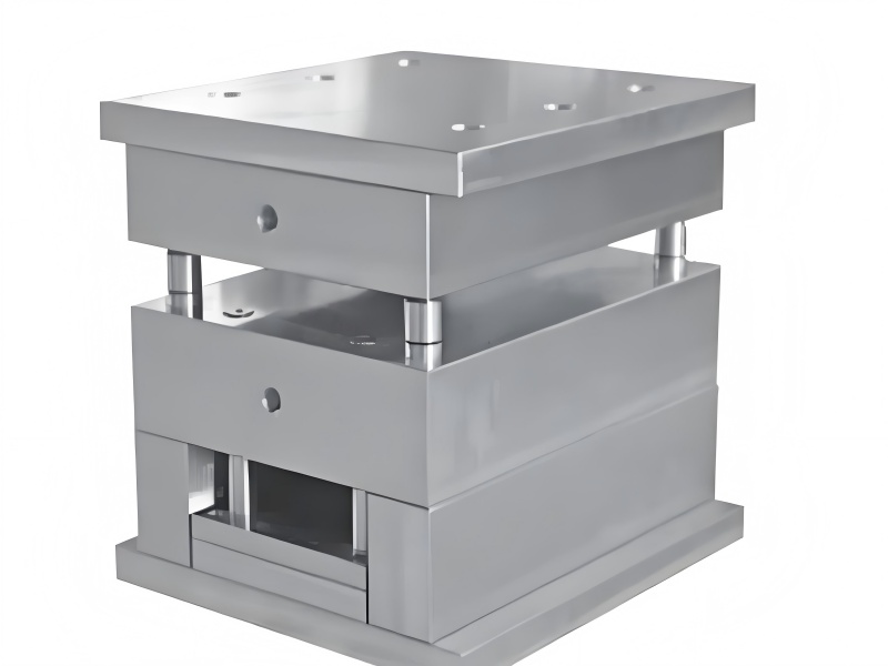
Mould Assembly Drawing
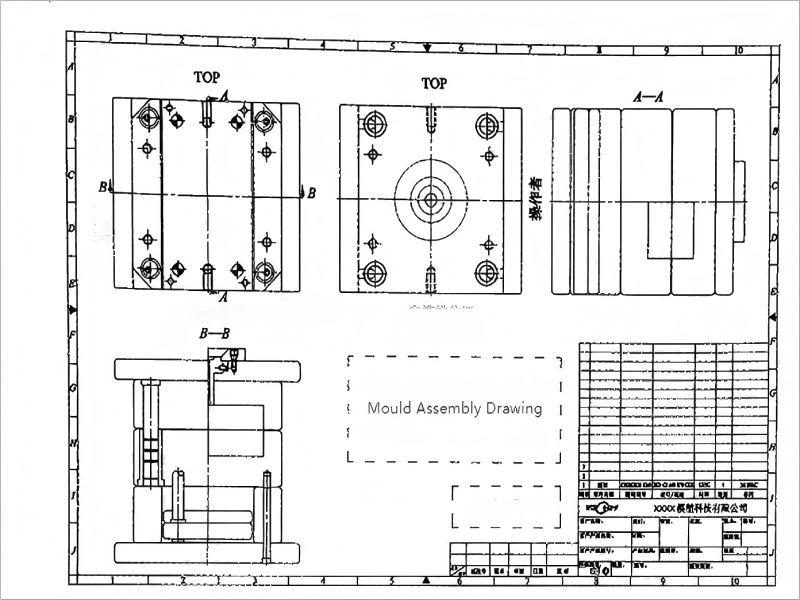
Status
The core drawing in mould design, created at a 1:1 scale. This comprehensive document brings together all elements of the mould design into a single cohesive representation.
Drawing Premises
Study customer's plastic part drawings + technical requirements, reference similar mould documents; revise plastic part drawings (add draft angles, convert tolerances, optimize shapes).
Cavity Drawing Conversion
Plastic part drawing → cavity drawing, first multiply by (shrinkage rate + 1), then mirror process to avoid moving/fixed mould misalignment – a critical step in accurate mould design.
Layout Requirements
Cavity drawing datum aligned with mould base datum (rounded); multi-cavity moulds should be numbered, with runners corresponding to cavity numbers (e.g., CAV.No.1). Proper alignment ensures functional accuracy in the final mould design.
Detail Processing
Magnify细微 structures; clearly dimension angle ejector layouts to avoid interference; mark hole positions with codes (e.g., support pillars marked SP, see Table 1-4). Attention to detail in these areas distinguishes professional mould design.
Complete Content
- Sufficient graphics to express mould structure
- Complete and accurate dimensions
- Ejector list (flat ejectors, supported ejectors, ejector sleeves must be clearly marked, preferably automatically generated)
- Part numbers, title block, parts list, revision block
- Cooling waterway axonometric drawing + venting diagram (in special cases)
- Hole positions and codes (see Table 1-4)
Table 1-4: Common Hole Positions and Their Codes in Mould Assembly Drawings
| Code | Name | Code | Name | Code | Name |
|---|---|---|---|---|---|
| S.P | Support Pillar | EGP | Ejector Plate Guide Pillar | LK | Nylon Lock |
| K.O | Knockout Hole | BIB | Square Locating Block | WL | Cooling Water Hole |
| STR | Ejector Plate Stop Pin | P.B | Sprue Stripper Plate Stop Screw | R.P | Return Pin |
| STP | Ejector Plate Stop Pin | T.L | Backing Plate | O.S | Offset Hole |
| EWP | Ejector Plate Screw | SW | Screw Hole | G.P | Guide Pillar |
| EGB | Ejector Plate Guide Bushing | S-A | Small Tie Bar | G.B | Guide Bushing |
Line Standards
Common line widths and applications are shown in Table 1-5 (GB/T 4457.4—2002). Line colors within the company must be standardized to maintain consistency in mould design documentation.
Table 1-5: Common Line Widths and Applications in Mould Design Drawings
| Line Name | Line Form | Code | Width | Applications (Examples) |
|---|---|---|---|---|
| Thick Solid Line | Solid | A | d | Visible contour lines, transition lines |
| Thin Solid Line | Solid | B | Approx. d/2 | Dimension lines, section lines, thread root lines, etc. |
| Wave Line | Wave | C | Approx. d/2 | Fracture boundary lines, view/section boundary lines |
| Double Zigzag Line | Double zigzag | D | Approx. d/2 | Fracture boundary lines |
| Dashed Line | Dashed | F | Approx. d/2 | Invisible contour lines, transition lines |
| Thin Chain Line | Chain | G | Approx. d/2 | Axes, symmetry center lines, trajectory lines |
| Thick Chain Line | Thick chain | J | d | Special requirement lines/surfaces |
| Double Dot Chain Line | Double dot chain | K | Approx. d/2 | Adjacent part contours, limit positions, blank contours, etc. |
Note: d can be 0.13mm, 0.18mm, etc.; common layouts for mould assembly drawings are shown in Figure 1-5.
Component Drawings
Status
Core production documents that must clearly express component structures. These detailed drawings are essential for manufacturing each part according to the mould design specifications.
Requirements
- Minimize the number of views; add 3D views for complex components
- Dimensions must be correct, complete, and clear
- Technical requirements:
- Specify draft angles
- Surface roughness
- Tolerances (precision/general/rough grades, unmarked tolerances follow GB/T 1800.1—2009 TT12)
- Geometric tolerances (required for type 101/102 moulds)
- Heat treatment/surface treatment (e.g., quenching to 48~50HRC)
Each component drawing in a mould design package must include all necessary information for manufacturing without requiring additional clarification. This includes material specifications, heat treatment requirements, and any special processing instructions.
Wire EDM Drawings
Requirements
Double dot chain lines represent plastic part contours, solid lines represent wire cutting areas; mark wire threading hole positions/dimensions, wire cutting outline dimensions (complex curves may be omitted).
Contour lines use 1.5d thick solid lines. These specialized drawings are critical in mould design for accurately producing complex shapes that require wire electrical discharge machining.
Wire EDM drawings in mould design must clearly indicate the starting point, cutting direction, and any necessary offsets to account for wire diameter. They should also specify the required surface finish and any critical dimensions that must be maintained after the EDM process.
Ejector Pin Layout Drawing
Application Scenarios
Separately drawn when the number of ejector pins > 20, spacing is too close, or insert ejectors require combined processing. This specialized layout ensures proper ejection system design in complex mould design projects.
The ejector layout is a critical aspect of mould design that ensures proper part release from the mould. This drawing should clearly indicate the type, size, and position of each ejector component, as well as their relationship to other mould features like cooling lines and core pulls.
In mould design, the ejector layout must balance sufficient force distribution to prevent part deformation with the need to avoid interference with other mould components. Proper spacing and positioning are essential for reliable mould operation and high-quality part production.
Electrode Drawings
Application Scenarios
Required for type 101/102 moulds, complex/large moulds. Electrodes are essential for creating intricate details in mould design that cannot be produced through conventional machining.
Requirements
Include EDM erosion diagram (indicating erosion method) + measurable dimensions. These drawings in mould design must specify electrode material, dimensions, and any special coating requirements.
Electrode drawings should also indicate the reference datums for setting up the EDM process, as well as the required火花间隙 (spark gap) for achieving the desired dimensions. Proper electrode design is crucial for achieving the required surface finish and detail resolution in mould design.
3D Model Drawings
Plastic Parts
For complex plastic parts, 3D solid models are created using UG/Pro/E. 3D modeling has become an essential part of modern mould design, enabling better visualization and analysis.
Moulds
Complex moulds/CNC machined moulds require 3D models, including at minimum:
- Moving and fixed mould inserts, cores, A/B plates
- For side core pulling moulds: slider inserts/holders
- For angle ejector moulds: angle ejectors/holders/ejector retainers
- All shapes except ejector holes, screw holes, and chamfers must be modeled
- 3D and 2D drawing names must match
3D models in modern mould design offer numerous advantages, including interference checking, automatic 2D drawing generation, and the ability to perform simulations for mould flow analysis. This digital approach enhances accuracy and reduces development time in mould design projects.
The 3D model should be a complete digital representation of the mould design, including all components and their relationships. This allows for virtual assembly verification before any physical manufacturing begins, helping to identify and resolve potential issues early in the mould design process.
© 2023 Mould Design Documentation Standards. All rights reserved.