Plastic Injection Mold Design Drawing Standards
A comprehensive guide to the industry's most mature and perfect standards for injection mold design documentation
1.1 General Provisions for Injection Mold Design Drawings
1.1.1 Drawing Size Specifications, Title Blocks, and Revision Blocks
In the field of mold design, standardized drawing sizes, title blocks, and revision blocks are fundamental to ensuring clear communication between design teams, manufacturers, and clients. The international standard sizes, such as A3 (297 x 420 mm) and A2 (420 x 594 mm), are commonly used for mold design drawings to facilitate easy handling and storage.
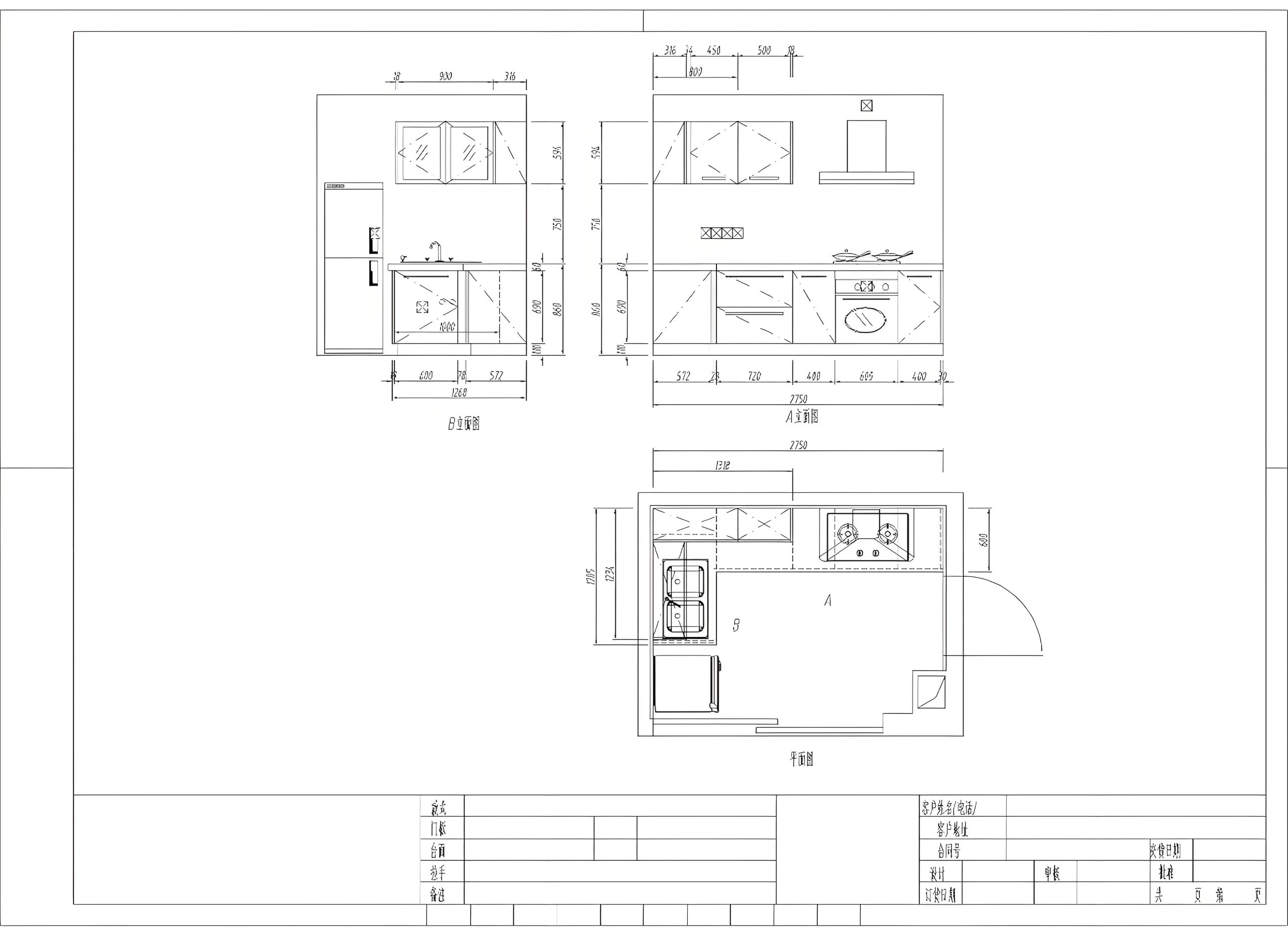
Figure 1: Standard drawing sheet layout with title block and revision block
The title block typically includes essential information such as the mold design project name, part number, material specifications, scale, designer's signature, and approval dates. Revision blocks are used to track changes made to the drawing over time, including the date of revision, description of changes, and the initials of the person making the changes.
1.1.2 Injection Mold Classification
Injection molds can be classified into several types based on their structure, function, and the number of cavities. Understanding this classification is crucial in mold design as it directly influences the complexity of the mold, production efficiency, and cost.
Two-Plate Molds
The simplest and most common type of injection mold, consisting of two main plates: the stationary platen (A plate) and the moving platen (B plate). These molds are suitable for most general-purpose mold design applications.
Three-Plate Molds
Feature an additional plate between the stationary and moving platens, allowing for more complex gating systems and the automatic separation of the runner system from the molded part. Ideal for mold design requiring precise gate locations.
Hot Runner Molds
Utilize a heated runner system to keep the plastic molten from the injection unit to the mold cavities, eliminating the need for runner ejection and reducing material waste. Commonly used in high-volume mold design projects.
Family Molds
Contain multiple cavities for different parts within a single mold. Careful mold design is required to ensure balanced filling and proper part ejection for each cavity.
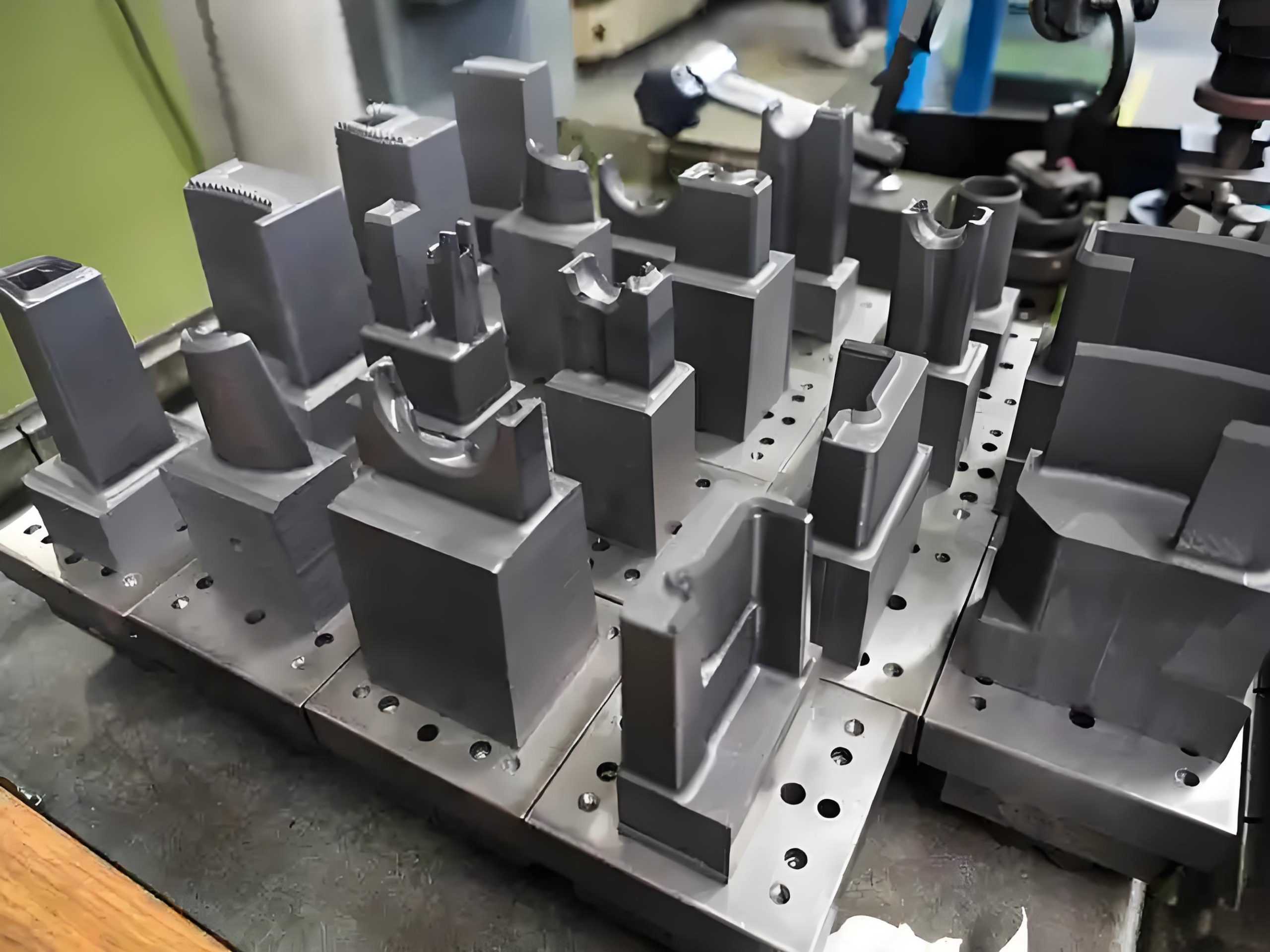
Figure 2: Common types of injection molds used in industrial applications
1.1.3 Types and Basic Requirements of Mold Design Drawings
Mold design drawings are essential documents that convey the detailed specifications of a mold. They include various types of drawings, each serving a specific purpose in the mold design and manufacturing process.
Assembly Drawings
Provide an overview of the entire mold structure, showing how all components fit together. Assembly drawings in mold design typically include dimensions for the overall mold size, cavity layout, and key component relationships.
Component Drawings
Detail the specifications of individual mold components, such as cavities, cores, ejector pins, and cooling channels. These drawings include precise dimensions, tolerances, surface finishes, and material specifications critical for mold design accuracy.
Section Drawings
Illustrate internal features of the mold that cannot be clearly shown in standard views. Section drawings are particularly important in mold design for depicting complex geometries, such as undercuts or intricate cooling systems.
Exploded View Drawings
Show the individual components of the mold in a disassembled state, clearly indicating their relationships and assembly sequence. These drawings aid in mold design verification, assembly, and maintenance processes.
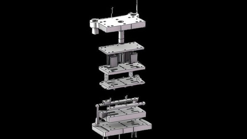
Figure 3: An example of a detailed injection mold assembly drawing
Basic requirements for all mold design drawings include clarity, completeness, accuracy, and compliance with relevant industry standards. Each drawing must be labeled with appropriate titles, scales, and notations to ensure that it can be easily understood and interpreted by all stakeholders involved in the mold design and manufacturing process.
1.1.4 Management of Mold Design Drawings
Effective management of mold injection design drawings is critical for maintaining version control, ensuring traceability, and facilitating collaboration among team members. In modern mold design practices, digital document management systems (DMS) are commonly used to store, organize, and track changes to design documents.
Version Control
Each revision of a mold design drawing must be clearly identified and tracked. Version control systems in mold design typically use a numbering scheme (e.g., 1.0, 1.1, 2.0) to indicate major and minor changes, ensuring that all team members are working with the latest iteration of the drawing.
Access Control
Restricting access to mold design drawings based on user roles and responsibilities helps protect sensitive information and ensures that only authorized personnel can make changes. This is particularly important in mold design projects involving proprietary designs or confidential client information.
Backup and Archiving
Regularly backing up mold design drawings and archiving older versions is essential for data security and compliance with industry regulations. Archiving also allows for historical reference in case of issues with the current mold design or during the development of future mold design projects.
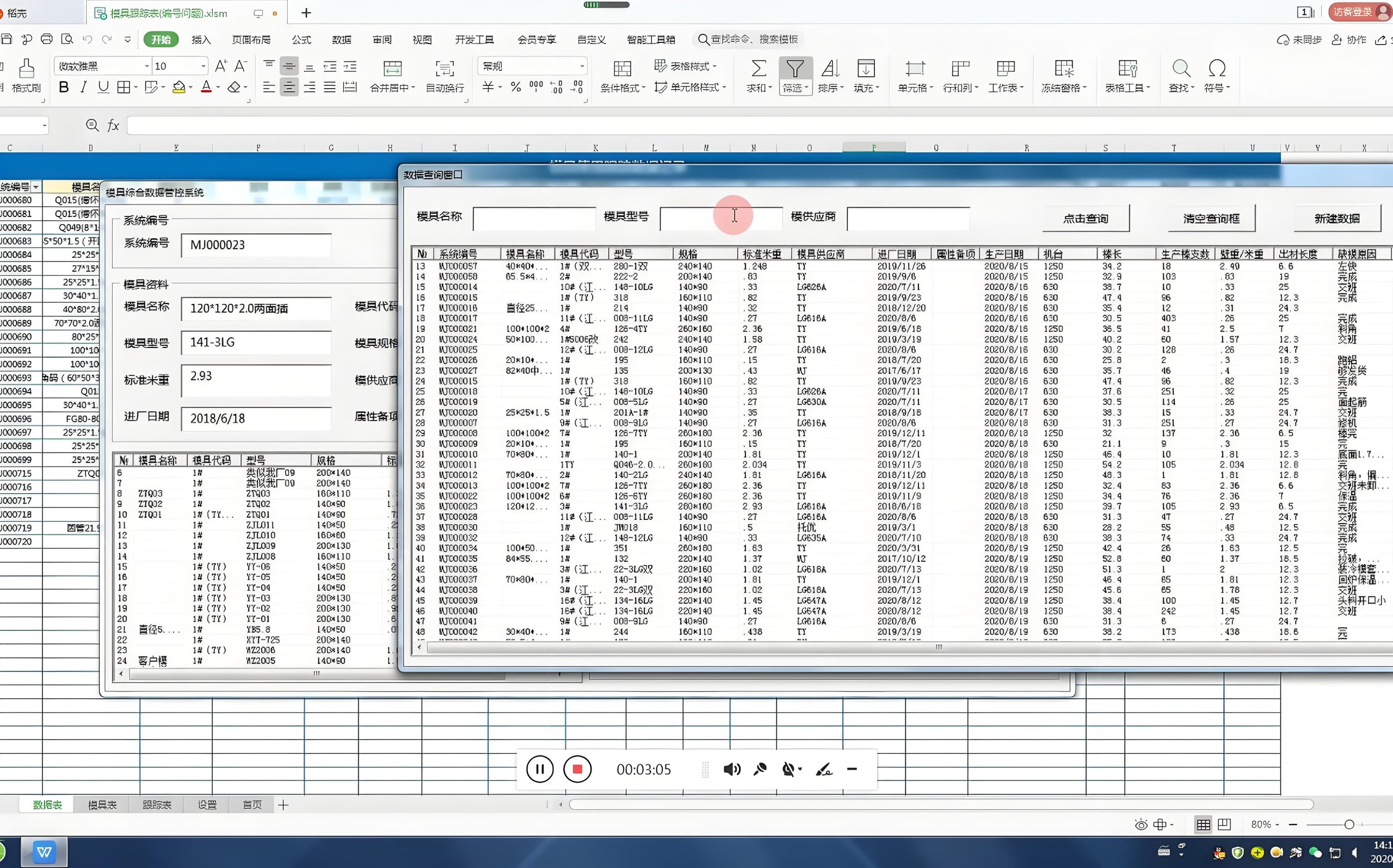
Figure 4: A typical interface of a mold design document management system
Additionally, clear documentation of the approval process for mold design drawings is necessary. This includes obtaining sign-offs from relevant stakeholders, such as design engineers, project managers, and clients, before the mold design proceeds to the manufacturing phase. Proper management of mold design drawings ensures efficiency, reduces errors, and maintains the integrity of the mold design process from concept to production.
1.2 General Process of Mold Design Drawing
1.2.1 Organize and Inspect Customer Data
The first step in any molding process project is to thoroughly review and organize the customer's requirements. This includes understanding the part geometry, material specifications, production volume, and any specific quality or performance requirements.
Part Geometry Analysis
Analyzing the part geometry is crucial to identify features that may affect mold design, such as undercuts, thin walls, or complex surfaces. Advanced software tools, such as CAD/CAM systems, are used to simulate the injection molding process and optimize the part design for manufacturability.
Material Selection
The choice of material directly impacts mold design considerations, including shrinkage rates, cooling requirements, and ejection methods. Collaborating with the customer to select the appropriate material ensures that the mold is designed to produce parts that meet the required specifications.
Production Volume Assessment
The expected production volume influences decisions regarding the number of cavities, type of gating system, and overall mold design complexity. High-volume production typically requires multi-cavity molds and automated systems to maximize efficiency.
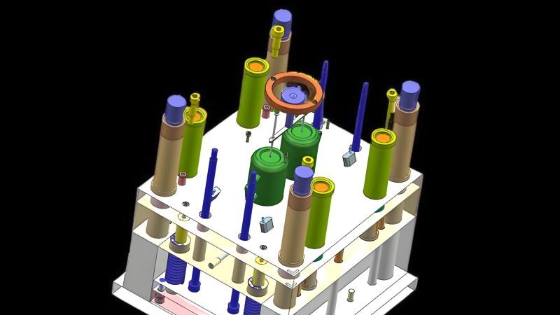
Figure 5: Analyzing customer-provided 3D models for mold design feasibility
Any discrepancies or ambiguities in the customer data must be resolved through clear communication with the client. This ensures that the mold design process proceeds smoothly and that the final mold meets all expectations.
1.2.2 Mold Drawing Preparation
Once the customer data is verified and analyzed, the next step is to create detailed mold drawings. This involves translating the part design into a comprehensive set of technical drawings that specify every component of the mold.
Initial Layout Design
The initial layout design establishes the overall structure of the mold, including the size and type of the mold base, cavity arrangement, gating system, and ejection mechanism. This phase of mold design requires careful consideration of factors such as part symmetry, cooling efficiency, and ease of assembly.
Component Design
Detailed design of individual mold components, such as cavities, cores, slides, and inserts, is based on the part geometry and functional requirements. Each component must be designed to precise specifications to ensure proper mold design functionality and durability.
Cooling and Heating System Design
Efficient cooling and heating systems are critical for optimizing cycle times and ensuring uniform part quality. Mold design engineers use advanced simulation tools to model heat transfer and fluid flow within the mold, allowing them to design effective cooling channels and temperature control systems.
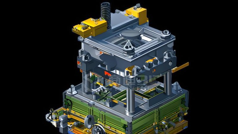
Figure 6: Using 3D modeling software to create detailed mold component designs
Throughout the drawing preparation process, adherence to standardized symbols, notations, and conventions is essential to ensure clarity and consistency. This facilitates communication among team members and reduces the risk of errors during the manufacturing phase of the mold design project.
1.2.3 Mold Design Drawing Standards
Adhering to established mold design drawing standards is critical to ensure that the drawings are accurate, complete, and consistent. These standards govern various aspects of the drawing, including dimensioning, tolerancing, surface finish, and material specifications.
Geometric Dimensioning and Tolerancing (GD&T)
GD&T is a system for defining and communicating engineering tolerances in mold design. It uses a symbolic language on engineering drawings to precisely describe part geometry and allowable variations, ensuring that the mold components fit together correctly and function as intended.
Surface Finish Symbols
Surface finish symbols indicate the required texture or smoothness of mold surfaces. Proper surface finish is crucial in mold design for achieving the desired part appearance, facilitating part ejection, and preventing defects such as sticking or surface blemishes.
Material Specifications
Clear specification of materials for each mold component is essential. This includes not only the base material but also any required heat treatments, coatings, or surface modifications. Proper material selection is vital for ensuring the durability and performance of the mold in mold design applications.
Standardized Component Sizing
Using standardized sizes for components such as screws, pins, and ejector plates simplifies the manufacturing process and reduces costs. Many mold design standards organizations provide guidelines for component sizing to ensure compatibility and interchangeability.
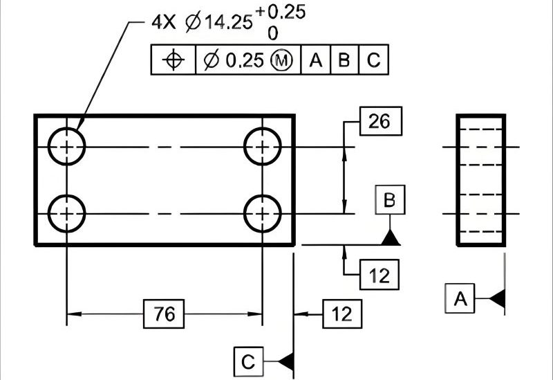
Figure 7: Common GD&T symbols used in mold design drawings
By following these standards, mold design professionals ensure that their drawings are universally understandable and can be accurately interpreted by manufacturers, inspectors, and other stakeholders involved in the production process.
1.2.4 Mold Design Drawing Inspection
A thorough inspection of mold design drawings is essential to identify and correct any errors or omissions before the manufacturing process begins. This inspection involves multiple levels of review by different stakeholders to ensure the accuracy and completeness of the mold design.
Design Verification
The initial review focuses on verifying that the mold design meets the customer's requirements and adheres to mold design standards. This includes checking the part geometry, material specifications, and functional requirements to ensure that the mold will produce parts that meet the desired quality standards.
Technical Review
A technical review assesses the feasibility of the mold design from a manufacturing perspective. This involves evaluating factors such as toolability, ease of assembly and disassembly, accessibility for maintenance, and the practicality of the proposed manufacturing processes.
Tolerance Analysis
Analyzing the tolerances specified in the mold design drawings is critical to ensure that the assembled mold will function correctly. This includes checking dimensional tolerances, geometric tolerances, and fits between components to prevent issues such as misalignment or interference during operation.
Simulation and Testing
Advanced simulation tools are used to test the mold design under various operating conditions. This may include flow simulation to analyze plastic melt flow, thermal analysis to evaluate cooling efficiency, and structural analysis to ensure the mold can withstand the pressures involved in the injection molding process.
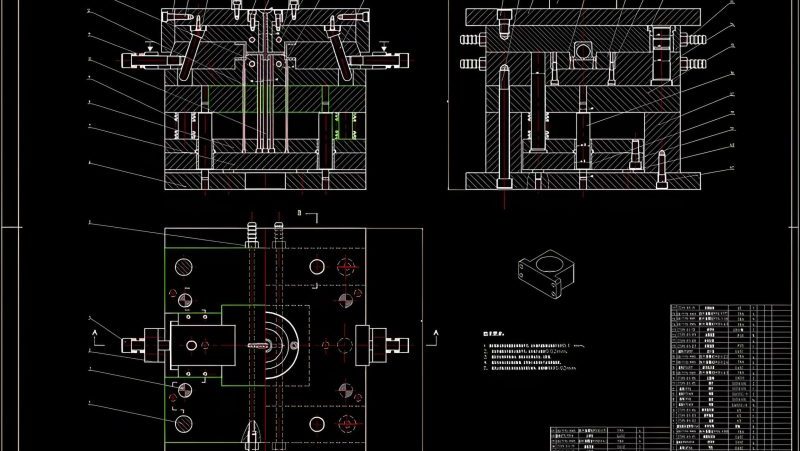
Figure 8: Flow simulation results used to verify and optimize mold design
Any issues identified during the inspection process are documented and addressed through revisions to the mold design drawings. This iterative process ensures that the final mold design is robust, reliable, and capable of producing high-quality parts efficiently.
1.2.5 Mold Production Follow-up
Once the mold design drawings are finalized and approved, the manufacturing process begins. However, the role of the mold design engineer does not end here. Continuous follow-up during production is essential to ensure that the mold is manufactured according to the specifications and to address any issues that arise.
Manufacturing Monitoring
Regular communication with the manufacturing team allows the mold design engineer to monitor progress and address any challenges that may arise during machining, assembly, or testing. This proactive approach helps prevent delays and ensures that the mold meets the required quality standards.
Prototype Testing
Once the mold is assembled, prototype parts are produced and tested to evaluate the mold's performance. The mold design engineer analyzes the prototype parts for defects, dimensional accuracy, and functionality, making any necessary adjustments to the mold design based on the test results.
Documentation Updates
Any changes made to the mold during production or testing are documented, and the design drawings are updated accordingly. This ensures that the as-built mold is accurately represented in the documentation, which is essential for future maintenance, repairs, and modifications to the mold design.
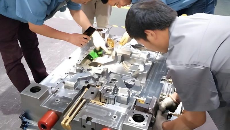
Figure 9: Inspecting prototype parts to verify mold performance
Effective production follow-up ensures that the final mold meets all specifications and performs as expected in production environments. This comprehensive approach to mold design and production results in a high-quality mold that delivers consistent, reliable performance over its service life.
1.3 Dimensioning in Mold Design Drawings
1.3.1 General Requirements for Dimensioning in Mold Design
Accurate dimensioning is critical in mold design to ensure that mold components are manufactured to the correct specifications and fit together properly. Dimensioning must be clear, complete, and consistent, following established industry standards.
Designing for injection molding.Clarity
Dimensions should be placed in a manner that avoids crowding and ensures they are easily readable. Arrows, leaders, and text should be of appropriate size and proportion to the drawing. In mold design, this often requires careful planning of the drawing layout to accommodate all necessary dimensions without confusion.
Completeness
Every feature of the mold component must be fully dimensioned. This includes not only linear dimensions but also angular dimensions, radii, and tolerances. Omitting a dimension in mold design can lead to manufacturing errors and costly delays.
Consistency
Using a consistent dimensioning method throughout the drawing set is essential. This includes standardizing the placement of dimensions, the use of symbols and notations, and the units of measurement. In mold design, consistency ensures that all stakeholders interpret the drawings correctly.
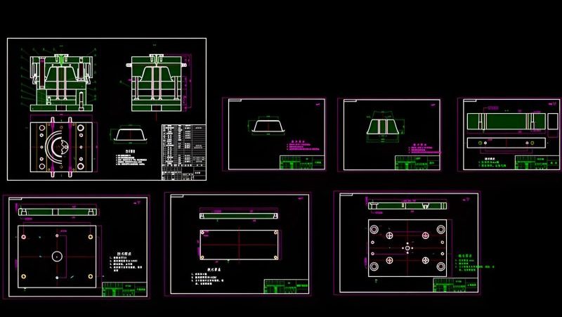
Figure 10: Example of clear and consistent dimensioning in a mold component drawing
Additionally, dimensions in mold design should be based on functional requirements and manufacturing capabilities. They should define the part's critical features and allowances necessary for proper assembly and operation of the mold.
1.3.2 Assembly Drawing Dimensioning Requirements
Assembly drawings in mold design require specific dimensioning practices to communicate how individual components fit together and function as a complete unit. These dimensions focus on overall mold size, critical clearances, and component relationships.
Overall Dimensions
The overall dimensions of the mold, including length, width, and height, are essential for determining the mold's compatibility with injection molding machines. These dimensions must be clearly specified in the assembly drawing to ensure proper installation and operation in mold design applications.
Critical Clearances
Clearances between moving parts, such as slides, ejector pins, and cores, must be accurately dimensioned. Insufficient clearances can lead to binding or premature wear, while excessive clearances can result in part defects or poor mold performance. Proper dimensioning of these clearances is vital in mold design for ensuring smooth operation and longevity of the mold.
Component Relationships
Dimensions that define the relative positions of components, such as cavity spacing, core alignment, and gate locations, are critical for ensuring that the mold produces parts with the correct geometry and dimensional accuracy. These dimensions must be precisely specified in the assembly drawing to guide the manufacturing and assembly processes in mold design.
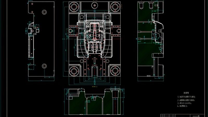
Figure 11: Key dimensions to include in a mold assembly drawing
Assembly drawings in mold design typically do not include detailed dimensions for individual components, as these are provided in component drawings. Instead, assembly dimensions focus on the mold's overall functionality and how the components interact.
1.3.3 Part Dimensioning Requirements
Component drawings in mold design require detailed and precise dimensioning to ensure that each part is manufactured to the exact specifications needed for proper mold function. These dimensions must account for manufacturing processes, material properties, and assembly requirements.
Functional Dimensions
Dimensions that directly affect the part's function, such as mating surfaces, hole sizes, and critical clearances, must be tightly controlled and clearly specified. In mold design, these dimensions often require tighter tolerances to ensure proper fit and operation.
Manufacturing Considerations
Dimensions should be provided in a way that facilitates manufacturing processes. This may include specifying dimensions that align with standard tooling sizes or machining operations. For example, in mold design, holes may be dimensioned to match standard drill bit sizes to simplify production.
Material Shrinkage Compensation
Injection molded parts undergo shrinkage as they cool. Mold components must be dimensioned larger than the desired part size to compensate for this shrinkage. The amount of compensation depends on the material used, part geometry, and processing conditions, and must be accurately calculated and applied in mold design.
Tolerance Specification
Every dimension in a component drawing should include an appropriate tolerance. Tolerances in mold design must be tight enough to ensure proper function but not unnecessarily restrictive, which can increase manufacturing costs.
Proper dimensioning of mold components is essential for ensuring interchangeability, ease of assembly, and long-term reliability. In mold design, even minor dimensional errors can lead to significant problems in the final product, making precise dimensioning a critical aspect of the design process.
1.3.4 Dimensioning Examples in Mold Design Drawings
To illustrate the principles of dimensioning in mold design, consider the following examples that demonstrate proper practices for different types of mold components and assemblies.
Cavity Block Dimensioning
A cavity block is a critical component in injection molds, as it forms the exterior shape of the molded part. Dimensioning a cavity block in mold design requires precise specification of the cavity geometry, including depth, width, length, and any undercuts or complex features. Additionally, the block itself must be dimensioned for proper fit within the mold base, including mounting holes and alignment features.
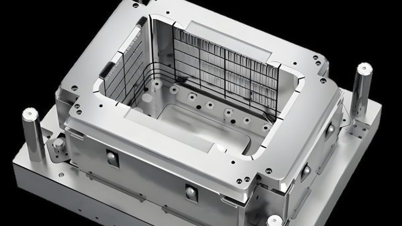
Figure 13: Dimensioning a cavity block with emphasis on critical features and mounting points
Ejector System Dimensioning
The ejector system in an injection mold is responsible for removing the molded part from the cavity. Proper dimensioning of ejector pins, blades, and sleeves is crucial in mold design to ensure smooth operation and prevent damage to the part. Key dimensions include the diameter and length of the ejector elements, their spacing, and the clearance between moving parts.
Hot Runner System Dimensioning
Hot runner systems require precise dimensioning to ensure proper melt flow and temperature control. In mold design, dimensions for hot runner nozzles, manifolds, and heaters must be carefully specified to maintain consistent plastic flow and prevent leaks or blockages. Critical dimensions include nozzle tip diameter, manifold layout, and heater placement.
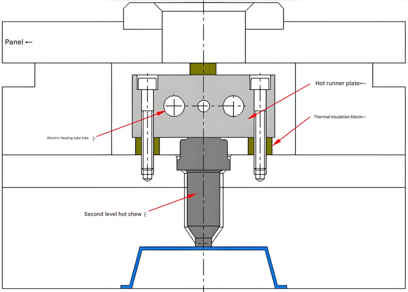
Figure 15: Dimensioning a hot runner system, showing key components and flow paths
These examples highlight the importance of accurate and detailed dimensioning in mold design. By following established standards and best practices, mold designers ensure that their drawings communicate the necessary information clearly and precisely, minimizing errors and ensuring the successful production of high-quality molds.
1.4 Tolerances and Fits in Injection Mold Design
1.4.1 Common Tolerances and Fits in Mold Assembly Drawings
In mold design, selecting appropriate tolerances and fits is crucial for ensuring that components assemble correctly, function as intended, and maintain their accuracy over time. Different components require different tolerance levels based on their function and interaction with other parts.
Precision injection molding.Clearance Fits
Clearance fits are used when components need to move freely relative to each other, such as ejector pins in bushings or slides in guideways. In mold design, typical clearance fits range from H7/g6 to H9/d9, depending on the required precision and the amount of movement needed.
Transition Fits
Transition fits are used when a small amount of interference or clearance is acceptable, such as for components that need to be assembled securely but may need to be disassembled for maintenance. Examples in mold design include locating pins and bushings, where a H7/k6 or H7/n6 fit is commonly used.
Interference Fits
Interference fits are used when components need to be permanently joined, such as inserts in cavity blocks or heating elements in hot runner manifolds. In mold design, interference fits like H7/p6 or H7/s6 are used to ensure a tight, secure connection that can withstand the stresses of the injection molding process.
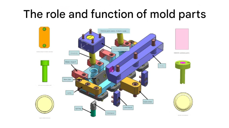
Figure 16: Common tolerance and fit applications in injection mold components
Proper selection of tolerances and fits in mold design ensures that components fit together correctly, minimizing wear, reducing the risk of failure, and improving the overall quality and performance of the mold.
1.4.2 Injection Mold Shrinkage Tolerances
Plastic materials shrink as they cool from the molten state to solid form, which must be accounted for in mold design. Shrinkage tolerances ensure that the final molded part meets the required dimensions despite this material behavior.
Factors Affecting Shrinkage
Shrinkage rates vary depending on several factors, including the type of plastic material, part geometry, wall thickness, mold temperature, and injection molding process parameters. In mold design, it is essential to consider these factors when determining the appropriate shrinkage compensation.
Calculating Shrinkage Compensation
Shrinkage compensation is typically calculated as a percentage increase in the mold cavity dimensions. For example, if a plastic material has a shrinkage rate of 1.5%, the mold cavity dimensions would be increased by 1.5% compared to the desired part dimensions. Accurate calculation of this compensation is critical in mold design to ensure part accuracy.
Tolerance on Shrinkage Compensation
Even with careful calculation, shrinkage can vary slightly due to process variations. Therefore, a tolerance is applied to the shrinkage compensation in mold design. Typical tolerances for shrinkage compensation range from ±0.05% to ±0.2%, depending on the material and application requirements.
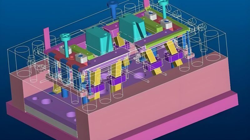
Figure 17: Illustration of how shrinkage compensation is applied in mold cavity design
Advanced simulation tools are often used in mold design to predict shrinkage patterns and optimize the compensation values, ensuring that the final parts meet the required dimensional specifications within acceptable tolerances.
1.4.3 Injection Mold Fit Tolerances
Fit tolerances in mold design determine how tightly components fit together and are critical for ensuring proper function, preventing leaks, and minimizing wear. Different types of fits are used for various mold components based on their function and requirements.
Sliding Fits
Components that slide relative to each other, such as ejector pins and slides, require precise sliding fits. In mold design, these fits typically have a small clearance to allow smooth movement while preventing excessive play, which could lead to misalignment or part damage. A common sliding fit tolerance is H7/f7.
Locational Fits
Components that need to be accurately positioned but do not require movement, such as cavity inserts and core pins, use locational fits. These fits provide a precise alignment while allowing for assembly and disassembly. A typical locational fit tolerance in mold design is H7/k6.
Press Fits
Press fits are used when components need to be permanently joined, such as bushings or sleeves in the mold base. These fits create an interference between the parts, ensuring a secure connection. In mold design, press fit tolerances like H7/p6 or H7/s6 are commonly used.
Sealing Fits
Components that need to prevent leaks, such as hot runner nozzles or cooling channels, require sealing fits. These fits must be tight enough to prevent plastic melt or coolant from escaping but not so tight as to cause damage. Sealing fit tolerances in mold design are typically more restrictive than standard locational fits.
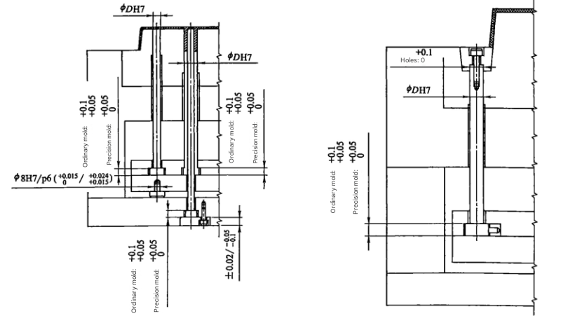
Figure 18: Different fit tolerances applied to various mold components
Proper selection and application of fit tolerances in mold design are essential for ensuring the mold's functionality, durability, and ability to produce high-quality parts consistently.
1.4.4 Mold Base Tolerances and Surface Roughness Requirements
Mold bases provide the structural foundation for the entire mold and must meet specific tolerance and surface roughness requirements to ensure proper alignment, support, and function of all components. In mold design, these requirements are critical for maintaining the mold's accuracy and longevity.
Dimensional Tolerances
Mold bases must be manufactured to tight dimensional tolerances to ensure proper fit with the injection molding machine and alignment of all components. Key dimensions, such as platen thickness, mounting hole locations, and overall size, are typically held to tolerances of ±0.05 mm to ±0.1 mm in mold design.
Flatness and Parallelism
The surfaces of the mold base that contact the injection molding machine platens must be flat and parallel to ensure even clamping force distribution. Flatness and parallelism tolerances in mold design are typically specified as ±0.02 mm per 100 mm of length or width.
Surface Roughness
Surface roughness requirements for mold bases depend on the specific application. Surfaces that mate with other components, such as locating rings or sprue bushings, typically require a finer finish, such as Ra 0.8 μm to Ra 1.6 μm. Non-critical surfaces may have a coarser finish, such as Ra 3.2 μm to Ra 6.3 μm in mold design.
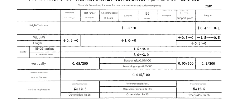
Figure 19: Critical dimensions and tolerances for a standard mold base
Adhering to these tolerance and surface roughness requirements in mold design ensures that the mold base provides a stable and accurate platform for all mold components, minimizing the risk of misalignment, premature wear, and part defects.
1.4.5 Common Geometric Tolerances in Mold Components
Geometric tolerances in mold design are used to control the form, orientation, location, and runout of features on mold components. These tolerances ensure that components fit together correctly and function as intended, even when dimensional tolerances are within acceptable limits.
Straightness
Straightness is critical for components such as ejector pins and guide pillars, which must move in a straight line. In mold design, straightness tolerances are typically specified as a maximum deviation from a perfectly straight line, often within ±0.01 mm per 100 mm of length.
Flatness
Flatness is important for surfaces that mate with other components, such as parting lines and mounting surfaces. In mold design, flatness tolerances ensure that these surfaces are planar within specified limits, typically ±0.02 mm to ±0.05 mm depending on the application.
Perpendicularity
Perpendicularity ensures that features are at right angles to each other, such as cores to parting lines or mounting holes to base surfaces. In mold design, perpendicularity tolerances are typically specified as a maximum angular deviation, often within ±0.05°.
Circularity and Cylindricity
Circularity and cylindricity are important for round features, such as holes, pins, and cores. These tolerances control the form of the feature to ensure it is perfectly circular or cylindrical. In mold design, circularity and cylindricity tolerances are typically specified as a maximum deviation from the ideal form, often within ±0.005 mm to ±0.01 mm.
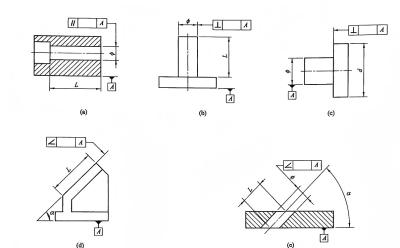
Figure 20: Examples of geometric tolerances applied to mold components
Proper application of geometric tolerances in mold design ensures that components function correctly, even when minor dimensional variations exist. This improves the overall quality and reliability of the mold and the parts it produces.
1.4.6 Surface Roughness of Mold Components
Surface roughness plays a critical role in mold design, affecting part quality, ease of ejection, and the lifespan of the mold. Different mold components require specific surface roughness values based on their function and interaction with the plastic material or other components.
Cavity and Core Surfaces
Cavity and core surfaces directly contact the plastic material and must have a smooth finish to ensure good part appearance and ease of ejection. In mold design, these surfaces typically require a surface roughness of Ra 0.2 μm to Ra 0.8 μm, depending on the part's aesthetic requirements and the type of plastic used.
Sliding Surfaces
Sliding surfaces, such as those on slides, ejector pins, and guide rails, require a balance between smoothness and lubricity. Too smooth a surface can cause sticking, while too rough a surface can lead to excessive wear. Surface roughness values for sliding surfaces in mold design typically range from Ra 0.8 μm to Ra 1.6 μm.
Cooling Channel Surfaces
Cooling channel surfaces affect heat transfer efficiency and the risk of corrosion. A smoother surface reduces the risk of buildup and improves coolant flow. In mold design, cooling channel surfaces usually have a surface roughness of Ra 1.6 μm to Ra 3.2 μm.
Figure 21: Surface roughness measurement and specifications for mold components
Achieving the correct surface roughness in mold design involves appropriate machining processes, such as grinding, polishing, or EDM, followed by careful surface treatment, if necessary, to ensure the mold performs optimally and produces high-quality parts.
1.4.7 Selection of Surface Roughness Values
Selecting the appropriate surface roughness values in mold design is critical for achieving the desired part quality, functionality, and mold lifespan. Several factors influence this selection, including the plastic material, part design, and manufacturing process.
Plastic Material Considerations
Different plastic materials have varying tendencies to stick to mold surfaces. For example, crystalline polymers like polyethylene and polypropylene may require smoother surfaces to prevent sticking, while amorphous polymers like ABS and polystyrene can tolerate slightly rougher surfaces. In mold design, the material's viscosity, shrinkage rate, and release properties must be considered when selecting surface roughness.
Part Design Requirements
The part's design, including its geometry, wall thickness, and aesthetic requirements, influences the required surface roughness. Parts with complex geometries or thin walls may require smoother surfaces to facilitate ejection and prevent deformation. High-gloss or textured finishes also dictate specific surface roughness values in mold design.
Manufacturing Process Constraints
The manufacturing processes used to produce the mold, such as machining, grinding, and polishing, have limitations on the achievable surface roughness. In mold design, the specified surface roughness must be feasible with the chosen manufacturing methods to ensure cost-effectiveness and practicality.
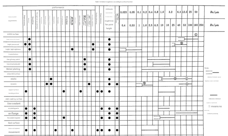
Figure 22: Guidelines for selecting appropriate surface roughness based on mold component function
By carefully considering these factors, mold designers can select the optimal surface roughness values in mold design, ensuring that the mold produces high-quality parts efficiently and reliably over its service life.
1.4.8 Other Requirements in Injection Mold Design
In addition to the specific tolerances, fits, and surface roughness requirements discussed, several other critical considerations must be addressed in mold design to ensure the mold's functionality, durability, and efficiency.
Material Selection
The choice of materials for mold components is critical and depends on factors such as the plastic material being molded, production volume, and required surface finish. Common materials include tool steels, stainless steels, and aluminum, each offering different properties such as hardness, corrosion resistance, and thermal conductivity. Proper material selection is fundamental in mold design for ensuring the mold's longevity and performance.
Heat Treatment
Many mold components require heat treatment to achieve the desired hardness, strength, and wear resistance. Heat treatment processes, such as quenching and tempering, must be carefully controlled to ensure consistent properties throughout the component. In mold design, specifying the correct heat treatment parameters is essential for optimizing component performance.
Surface Treatments
Surface treatments, such as nitriding, chrome plating, or PVD coating, can enhance the mold's performance by improving wear resistance, corrosion resistance, and release properties. The choice of surface treatment in mold design depends on the specific requirements of the application, such as the type of plastic material and the expected production volume.
Ejection System Design
The ejection system must be carefully designed to ensure that parts are ejected smoothly and without damage. This includes selecting the appropriate type of ejection mechanism (e.g., ejector pins, blades, or sleeves), determining their size and placement, and calculating the required ejection force. Proper ejection system design is critical in mold design for preventing part defects and ensuring efficient production.
Addressing these additional requirements in mold design ensures that the mold is not only dimensionally accurate but also functionally robust, capable of producing high-quality parts efficiently and reliably over an extended period.