Injection Molding Design Inspection Checklist
A comprehensive quality assurance framework for verifying mold designs before production in injection molding design processes. This checklist ensures all critical aspects of injection molding design are validated for optimal performance and quality.
Basic Information
Injection Molding Design Overview
This document serves as the primary inspection checklist for validating mold designs in injection molding design workflows. Proper completion ensures that all critical design elements meet specifications and industry standards for injection molding design. Thorough inspection at this stage prevents costly errors in production and ensures optimal part quality in injection molding design projects.
Plastic Part Inspection
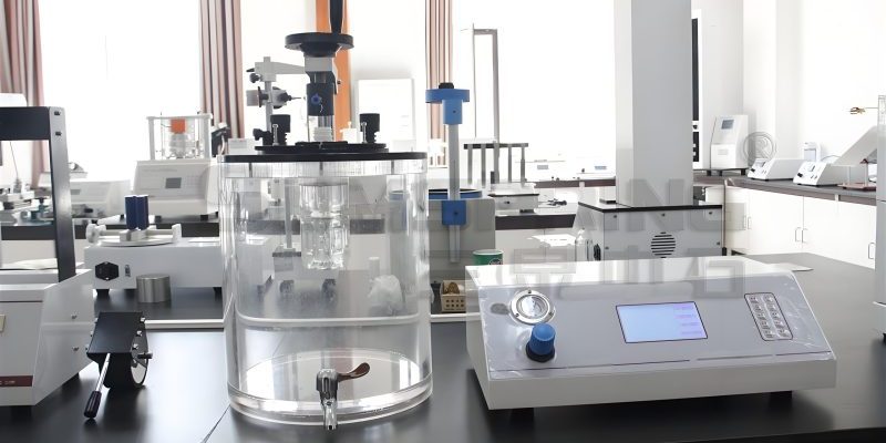
The plastic part inspection is a fundamental step in injection molding design verification. It ensures that the part geometry is optimized for the injection molding process, considering factors that affect moldability, dimensional stability, and overall quality. Each aspect of the part design must be carefully evaluated to prevent production issues in injection molding design.
Verify that all vertical surfaces have appropriate draft angles to facilitate easy ejection from the mold. Insufficient draft can cause part damage during ejection and increase cycle times in injection molding design. The required draft angle depends on material, surface finish, and part geometry in injection molding design.
Confirm that proper shrinkage factors have been applied to the mold design based on the specific plastic material being used. Incorrect shrinkage compensation leads to dimensional inaccuracies in the final part in injection molding design. Material data sheets should be consulted for accurate shrinkage values in injection molding design.
Inspect the location and design of parting lines to ensure they minimize visible flash, facilitate mold construction, and do not interfere with part functionality. The parting line should be positioned to simplify mold design in injection molding design. Proper parting line placement is critical for achieving desired part aesthetics in injection molding design.
Perform a thorough check to ensure that when this part is assembled with mating components, there are no interference issues. This includes checking both functional and aesthetic assembly requirements in injection molding design. Tolerance stack-ups should be analyzed for all critical assembly features in injection molding design.
Identify all undercut features and verify that appropriate mechanisms (such as slides or lifters) are included in the mold design to accommodate them. Minimizing undercuts where possible simplifies mold construction in injection molding design. Each undercut should have a corresponding solution in the mold design for injection molding design.
Check for uniform wall thickness throughout the part to prevent issues such as sink marks, warpage, and filling problems. Thickness transitions should be gradual to avoid stress concentrations in injection molding design. Wall thickness should be optimized for both structural integrity and molding efficiency in injection molding design.
Inspection Notes
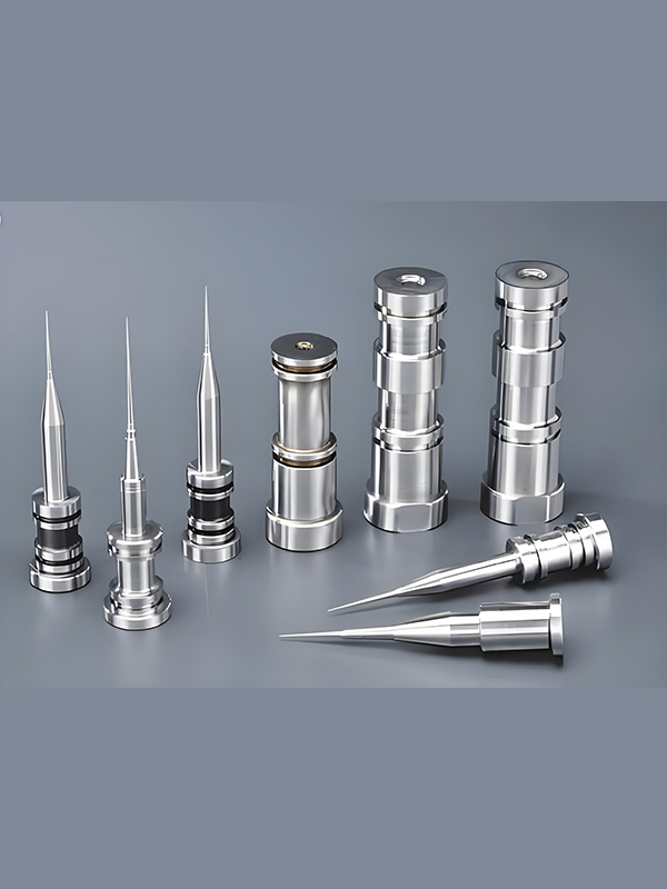
Inner Mold Insert Inspection
Inner mold inserts are critical components in injection molding design that directly shape the plastic part. Their proper design and placement ensure dimensional accuracy, surface quality, and efficient cooling. Thorough inspection of these elements is essential for successful injection molding design outcomes. Each insert must be checked for proper integration with the overall mold structure in injection molding design.
Verify proper placement, sizing, and spacing of screws, ejector pins, and cooling water channels.
Confirm accurate positioning of inserts and proper gate datum references.
Check that adequate venting is provided to prevent gas traps during molding.
Ensure proper placement and sizing of mold temperature sensor holes.
Verify proper clearance for ejector pins to ensure smooth operation.
Check that required part markings are correctly positioned and sized.
Confirm proper color coding for steel type identification (Color #10).
Verify shut-off and fitting surfaces are properly identified with Color #13.
Check that angled holes include appropriate servo positions for machining.
Verify proper design and placement of process threaded holes.
Ensure wire EDM inserts include proper radius features as specified.
Check gate puller pins for proper design and placement.
Verify 0.5mm clearance on sides of inserts above parting line.
Confirm engraved surfaces are raised by minimum 0.2mm for concave text.
Insert Material Specifications
Material distribution for inner mold components in injection molding design
Insert Inspection Notes
Side Action Mechanism Inspection
Critical Design Considerations
- Slider movement must be sufficient to clear all undercut features
- Wedge angles should be 2-3° greater than the angle of friction
- Cooling must be incorporated into slide components for consistent molding
- Proper guidance prevents binding during operation in injection molding design
Side action mechanisms, including slides and lifters, are essential for producing parts with undercuts in injection molding design. These components must be carefully designed to ensure reliable operation, proper part release, and long service life. Each aspect of the side action system requires thorough inspection to validate its suitability for the intended application in injection molding design.
Verify if clamping wedges can be standardized components to reduce costs and lead time.
Check that slider return springs have appropriate length for proper function and longevity.
Ensure slider components include adequate cooling to maintain proper mold temperatures.
Verify that slider keepers are standardized components where possible.
Check that slider tops include appropriate radius features to prevent stress concentrations.
Verify that sliders have proper positioning mechanisms for consistent operation.
Ensure sliders have adequate guidance to prevent binding during movement.
Check that large wedges have proper top positioning features.
Verify proper installation and material selection for slider wear plates.
Confirm insert positioning follows standard sizes based on CNC electrode dimensions.
Side Action Mechanism Inspection Notes
Mold Structural Components Inspection
The structural components of a mold form the foundation of its integrity and performance in injection molding design. These elements must be inspected for proper sizing, material selection, placement, and integration to ensure the mold can withstand the pressures and cycles of production. A thorough evaluation of these components is critical for achieving reliable, long-lasting performance in injection molding design applications.
Mold Structural Integrity Checklist
Specialized Mold Type Considerations
Two-Plate Mold Specifics
Three-Plate Mold Specifics
Structural Components Inspection Notes
Other Considerations
Beyond the major components, several additional factors contribute to the successful implementation of injection molding design. These include documentation standards, file organization, and special requirements that ensure clarity, consistency, and efficiency throughout the mold manufacturing and production processes. Attention to these details is essential for maintaining quality and reducing errors in injection molding design projects.
Verify that CAD files use proper layer separation for different components and features, facilitating clear communication between design and manufacturing teams in injection molding design. Proper layer organization enhances efficiency in both mold manufacturing and future modifications.
Confirm that complete assembly drawings and individual component drawings are included, each with proper dimensions, tolerances, and material specifications for injection molding design. These drawings serve as the primary reference for manufacturing and quality control processes.
Check that all project folders follow the specified naming convention with barcode numbers prepended to facilitate easy identification and tracking throughout the injection molding design process. Consistent naming conventions improve organization and reduce the risk of file mismanagement.
Documentation Compliance Checklist
Additional Notes & Considerations
Final Inspection Review
Inspector Information
Inspection Summary & Recommendations
Provide a summary of the inspection findings and any recommendations for improvements or required modifications to ensure compliance with injection molding design standards.
Inspection checklist version: 2.4.1
Last updated: May 15, 2023