Drawing Size Specifications
Standardization of drawing sizes is critical for effective communication and storage in mold design. The International Organization for Standardization (ISO) and American National Standards Institute (ANSI) provide the two primary systems for technical drawing sizes.
ISO Drawing Sizes
The ISO A series is based on a 1:√2 aspect ratio, providing consistent scaling.
ANSI Drawing Sizes
The ANSI standard provides a range of sizes suitable for industrial applications.
| ISO Size |
Dimensions (mm) |
ANSI Equivalent |
| A0 |
841 x 1189 |
4A0 |
| A1 |
594 x 841 |
2A0 |
| A2 |
420 x 594 |
A |
| A3 |
297 x 420 |
B |
| A4 |
210 x 297 |
C |
In molding design, the choice of drawing size depends on the complexity and scale of the mold. Larger molds typically require larger drawing sizes to maintain clarity and detail. However, it is essential to balance between detail and practicality, as oversized drawings can be cumbersome to handle and store.
Injection mold design requires precise communication of complex geometries, making standardized drawing sizes essential for ensuring that all stakeholders can accurately interpret the design intent. The use of standardized sizes also facilitates the integration of digital mold design software with traditional drafting practices, ensuring seamless collaboration between design teams, manufacturers, and clients.
Title Blocks
Title blocks are essential components of technical drawings, providing critical information about the mold design. They typically include:
- Mold Designer Information: Name, signature, and contact details of the designer or design team responsible for the mold.
- Company Information: Name, logo, and address of the manufacturing company or design firm.
- Mold Identification: Unique mold number, project name, and client information.
- Drawing Details: Drawing number, sheet number, and total number of sheets in the set.
- Scale and Projection: The scale at which the mold is drawn and the projection method used (e.g., first-angle or third-angle projection).
- Material Specifications: Details about the materials used in the mold construction.
- Tolerances: General tolerances applicable to the mold unless otherwise specified.
- Date: The date the drawing was created or last revised.
Typical Title Block Layout
A well-structured title block ensures all necessary information is clearly presented.
The title block is typically located in the bottom right corner of the drawing sheet, as this is the first area viewed when the drawing is properly oriented. Standardization of title block formats within an organization ensures consistency and facilitates quick identification of critical information.
In modern mold design processes, title blocks often include digital metadata that can be linked to databases, enabling efficient tracking of mold designs throughout their lifecycle. This integration of digital and traditional drafting elements is a key aspect of modern mold design practices, enhancing both accuracy and efficiency in the mold design workflow.
Revision Blocks
Revision blocks track changes made to the mold design over time. They are crucial for maintaining version control and ensuring that all stakeholders are working with the latest design iteration. A typical revision block includes:
- Revision Number: A unique identifier for each revision (e.g., Rev 0, Rev 1, Rev 2).
- Date: The date the revision was made.
- Description of Changes: A brief explanation of what was modified in the revision.
- Author: The name or initials of the person who made the revision.
- Approval: Space for signatures or approvals, if required.
Revision Block Structure
A revision block helps track the evolution of the mold design.
Revisions are typically numbered sequentially, with each new revision reflecting significant changes to the design. Minor corrections or clarifications may be noted without incrementing the revision number, depending on organizational policies.
Effective use of revision blocks is essential in injection mold design, where even minor changes can have significant implications for mold performance and production costs. By maintaining a clear record of all modifications, mold designers and manufacturers can ensure accountability, facilitate communication, and prevent errors caused by working with outdated information.
Incorporating mold design principles into the revision process ensures that each change is evaluated for its impact on the overall mold functionality, manufacturing feasibility, and cost. This systematic approach to revision management is a cornerstone of high-quality mold design practices.
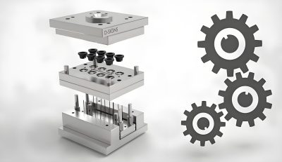
By Mold Structure
Injection molds can be classified based on their structural design, which determines how the mold opens, closes, and ejects the molded part. The primary types include:
Two-Plate Molds
The simplest and most common type of injection mold, consisting of two plates: the stationary (fixed) platen and the moving platen.
- Single cavity or multi-cavity designs
- Straightforward ejection system
- Most economical for simple parts
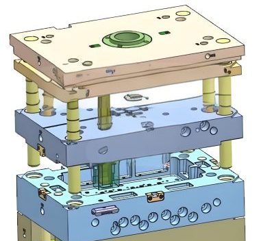
Three-Plate Molds
Feature an additional plate between the stationary and moving platens, allowing for automatic separation of the runner system from the part.
- Ideal for parts requiring gated runners
- More complex and expensive than two-plate molds
- Provides better part aesthetics
Hot Runner Molds
Utilize a heated manifold system to keep the plastic molten from the injection unit to the mold cavities, eliminating the need for runners.
- Reduces material waste and cycle time
- Higher initial cost but lower operational costs
- Common in high-volume production
Insulated Runner Molds
Similar to hot runner molds but use a thermal insulating layer to keep the plastic molten in the runner system.
- Lower cost than hot runner systems
- Requires careful temperature control
- Suitable for semi-crystalline polymers
By Number of Cavities
The number of cavities in a mold determines how many parts are produced in each injection cycle. This classification includes:
| Type |
Description |
Applications |
| Single Cavity |
One cavity producing one part per cycle |
Prototype development, large parts, low-volume production |
| Family Mold |
Multiple cavities for different but related parts |
Assemblies requiring multiple components |
| Multi-Cavity |
Identical cavities producing the same part |
High-volume production of small to medium parts |
| Stack Mold |
Multiple layers of cavities stacked in the mold |
Very high-volume production, maximizing machine usage |
The choice of cavity configuration depends on production volume requirements, part complexity, and cost considerations. Family molds, for example, are advantageous when producing multiple components of an assembly, as they allow all parts to be molded in a single cycle, ensuring consistency in material properties and color.
Injection mold design for multi-cavity molds requires careful consideration of flow balance to ensure uniform filling of all cavities. This involves precise calculation of runner sizes, gate locations, and cavity layouts to minimize variations in part quality. Advanced mold design software plays a crucial role in optimizing these parameters, ensuring efficient and consistent production across all cavities.
By Ejection System
The ejection system is responsible for removing the molded part from the mold. Common types include:
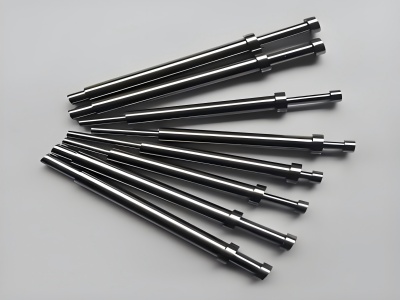
Pin Ejection
Uses ejector pins to push the part out of the mold cavity. Simple and widely used, but may leave marks on the part surface.
Sleeve Ejection
Utilizes a sleeve that surrounds the part to provide uniform ejection force, ideal for parts with deep bosses or cylindrical features.
Stripper Plate Ejection
Employs a stripper plate to push the part off the core, suitable for parts with large surface areas or delicate features.
Air Ejection
Uses compressed air to blow the part out of the mold, often used in conjunction with other ejection methods for delicate parts.
The selection of an ejection system is critical in mold design, as it directly impacts part quality, production efficiency, and mold longevity. Proper ejection system design ensures that parts are removed without damage, minimizing cycle times and reducing the risk of production delays.
Modern mold design practices often incorporate simulation tools to analyze ejection forces and optimize the ejection system layout. This approach helps identify potential issues early in the design process, allowing for adjustments that improve part quality and reduce manufacturing costs.
By Application
Injection molds can also be classified based on their specific applications, including:
Packaging Molds
Designed for producing packaging components such as bottles, caps, and containers. High precision and fast cycle times are critical.
Automotive Molds
Used for manufacturing automotive components, requiring high durability, precision, and often complex geometries.
Medical Device Molds
Produce components for medical devices, requiring strict compliance with hygiene standards and precision tolerances.
Consumer Goods Molds
Create everyday consumer products, focusing on aesthetics, functionality, and cost-effectiveness.
Each application-specific mold type has unique design considerations. For example, medical device molds must be designed for easy cleaning and sterilization, often using stainless steel materials and avoiding crevices where contaminants could accumulate. Automotive molds, on the other hand, often require large-scale production capabilities and the ability to mold high-strength materials.
Mold design for specific applications also involves considerations such as part complexity, surface finish requirements, and material compatibility. Advanced mold design techniques, such as conformal cooling and optimized gating systems, are often employed to meet the unique demands of each application, ensuring high-quality parts and efficient production processes.
Understanding the different classifications of injection molds is fundamental to effective mold design. By selecting the appropriate mold type based on structural requirements, cavity configuration, ejection system, and application, mold designers can optimize the manufacturing process, reduce costs, and ensure the production of high-quality plastic components.
Mold design drawings are essential for communicating the design intent to manufacturers and ensuring the accurate production of molds. The primary types of drawings include:
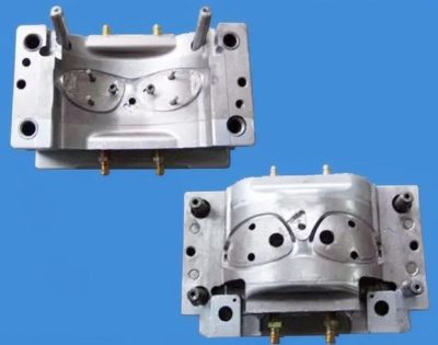
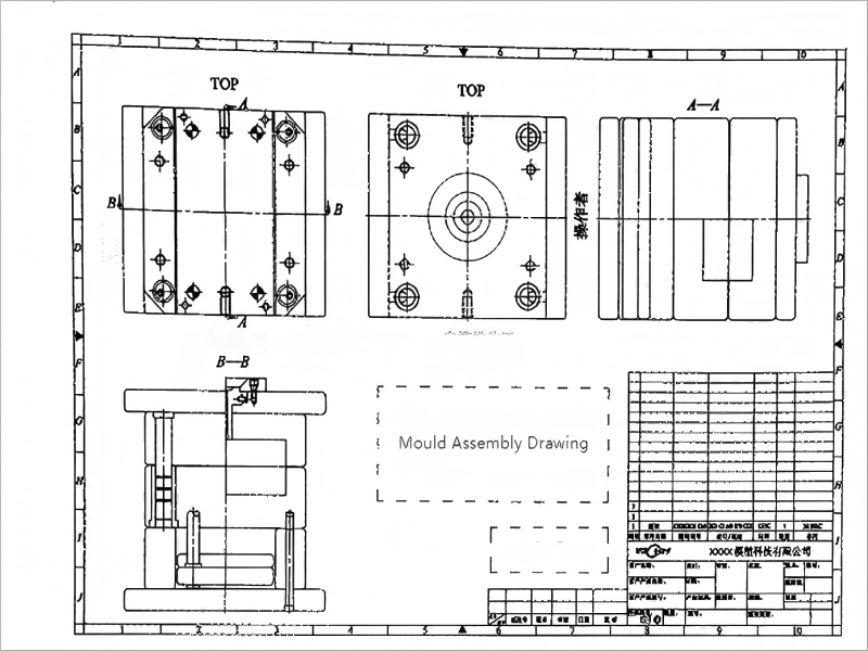
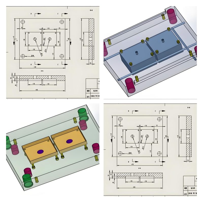
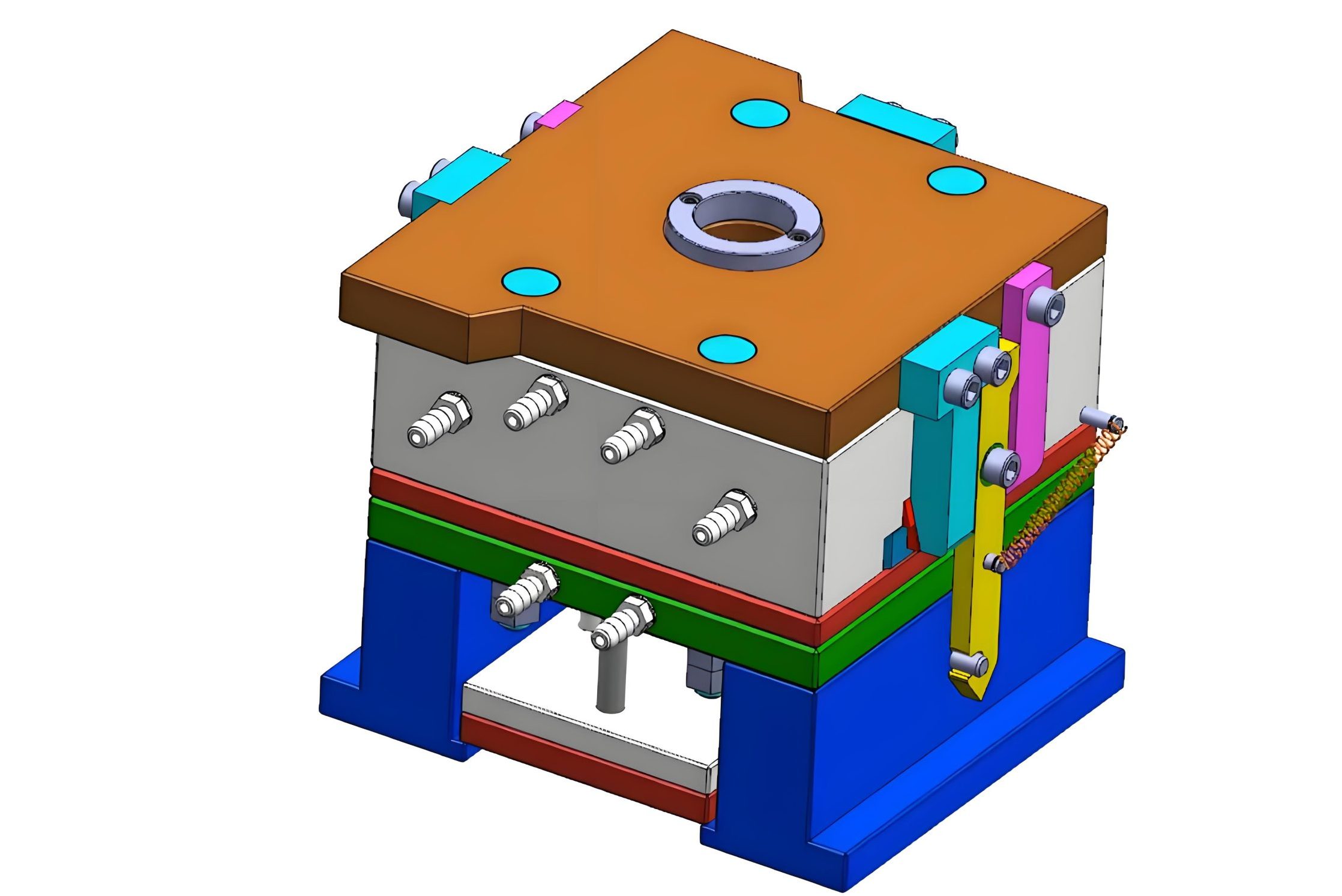
Assembly Drawings
Show the complete mold assembly, including all components and their relationships. They provide an overview of the mold structure and how it functions.
- Include views of the mold in both open and closed positions
- Show dimensions for critical components and overall mold size
- Indicate part numbers and references to detailed component drawings
Component Drawings
Provide detailed information about individual mold components, such as cores, cavities, ejector pins, and cooling channels.
- Include detailed dimensions, tolerances, and surface finish requirements
- Specify materials and heat treatment requirements
- Show critical features and their relationships to other components
Section Drawings
Illustrate internal features of the mold by showing a cross-section. These are particularly important for understanding complex geometries and internal structures.
- Reveal hidden features such as cooling channels, ejector mechanisms, and internal ribs
- Help in visualizing how different components fit together
- Essential for identifying potential interference issues
Detail Drawings
Focus on specific details of the mold, such as gate locations, runner systems, and ejection mechanisms. They provide in-depth information for critical areas.
- Show precise dimensions and tolerances for critical features
- Indicate surface finish requirements and material specifications
- May include annotations explaining design intent or manufacturing processes
Basic Requirements for Mold Design Drawings
To ensure clarity, accuracy, and usability, mold design drawings must meet several fundamental requirements:
Accuracy
Drawings must precisely represent the mold design, with accurate dimensions and tolerances. Even minor errors can lead to significant issues in mold production and performance.
Completeness
All necessary information must be included, such as dimensions, tolerances, materials, surface finishes, and assembly instructions. Missing information can result in delays and misunderstandings.
Clarity
Drawings should be easy to read and interpret, with clear views, proper scaling, and adequate annotations. Complex features should be simplified or broken down into understandable components.
Standardization
Adhere to industry standards (e.g., ISO, ASME) for drawing conventions, symbols, and terminology. Standardization ensures consistency and facilitates communication between different teams.
Traceability
Drawings should include revision histories, part numbers, and cross-references to other related documents. This allows for easy tracking of changes and ensures that all stakeholders are working with the latest information.
Digital Integration
Incorporate digital elements such as 3D models, parametric dimensions, and links to manufacturing databases. Digital integration enhances collaboration and streamlines the manufacturing process.
Geometric Dimensioning and Tolerancing (GD&T)
GD&T is a system for defining and communicating engineering tolerances. It uses a symbolic language on engineering drawings to precisely describe part geometry and allowable variations. Proper application of GD&T in mold design is critical for:
- Ensuring proper fit and function of mold components
- Communicating design intent clearly to manufacturers
- Minimizing manufacturing costs by specifying appropriate tolerances
- Facilitating interchangeability of components
- Improving quality control and inspection processes
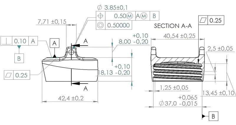
Common GD&T Symbols
Geometric Dimensioning and Tolerancing symbols provide precise control over part geometry.
Key GD&T concepts in mold design include:
Form Controls
- Straightness: Ensures a feature is straight within specified limits
- Flatness: Controls the flatness of surfaces
- Circularity: Ensures a cross-section of a cylinder is perfectly round
- Cylindricity: Controls the overall form of a cylinder
Orientation Controls
- Perpendicularity: Ensures features are at 90 degrees to a reference
- Parallelism: Controls the parallelism of features
- Angularity: Specifies an exact angle between features
Location Controls
- Position: Controls the location of features relative to a datum
- Concentricity: Ensures features share a common center axis
- Symmetry: Controls the symmetry of features about a center plane
Runout Controls
- Circular Runout: Controls the variation in surface profile during rotation
- Total Runout: Controls the cumulative variation in surface profile and axial alignment
Proper application of GD&T in mold design drawings ensures that critical dimensions and geometries are controlled to the necessary precision, reducing the risk of mold failures and ensuring the production of high-quality plastic parts. This is particularly important in industries such as automotive and medical devices, where precision and reliability are paramount.
Material and Heat Treatment Specifications
Mold design drawings must clearly specify the materials and heat treatment requirements for each component. This information is critical for ensuring the mold's durability, performance, and compatibility with the plastic material being molded.
| Component |
Typical Materials |
Heat Treatment |
| Cores and Cavities |
P20, H13, S7, 420 Stainless Steel |
Hardening to 28-32 HRC (P20), 48-52 HRC (H13) |
| Ejector Pins |
H13, D2, Stainless Steel |
Hardening to 52-56 HRC |
| Sprue Bushing |
H13, M2 Tool Steel |
Hardening to 48-52 HRC |
| Mold Base |
A36 Steel, 1045 Steel |
Normalizing or Stress Relieving |
| Hot Runner Components |
H13, Custom Alloys |
Hardening to 48-52 HRC |
Key considerations for material selection include:
- Wear Resistance: Cores and cavities require materials that can withstand the abrasive effects of molten plastic flow.
- Corrosion Resistance: For molding corrosive plastics like PVC, stainless steel materials are often necessary.
- Thermal Conductivity: Efficient heat transfer is critical for controlling cycle times and part quality.
- Strength and Toughness: Components must withstand high pressures and stresses during the injection molding process.
- Machinability: Materials should be easy to machine to achieve the required precision and surface finish.
Heat treatment specifications are equally important, as they determine the final properties of the mold components. Improper heat treatment can lead to premature wear, cracking, or deformation of the mold, resulting in costly repairs and production downtime.
Injection mold design drawings must clearly specify not only the material grades but also the exact heat treatment processes, including hardness requirements, tempering temperatures, and cooling rates. This ensures that manufacturers can produce mold components with the desired properties and performance characteristics.
Surface Finish Requirements
Surface finish plays a critical role in mold performance and part quality. The required surface finish depends on several factors, including:
- The desired appearance of the molded part
- The type of plastic material being molded
- The function of the molded part
- Ejection requirements
- The presence of text or logos on the mold surface

SPI Surface Finish Standards
The Society of the Plastics Industry (SPI) defines standard surface finishes for injection molds.
Common surface finish specifications include:
| Finish Class |
Description |
Ra Value (µin) |
Typical Applications |
| SPI-A-1 |
Mirror finish, polished with 0.05 µm diamond paste |
0.8-1.6 |
Optical components, transparent parts |
| SPI-A-2 |
High-gloss finish, polished with 0.1 µm diamond paste |
1.6-3.2 |
Cosmetic parts, clear housings |
| SPI-B-1 |
Fine matte finish, polished with 1500 grit paper |
3.2-6.3 |
General-purpose parts, textured surfaces |
| SPI-B-2 |
Medium matte finish, polished with 1000 grit paper |
6.3-12.5 |
Industrial parts, non-cosmetic surfaces |
| SPI-C-1 |
Coarse matte finish, polished with 600 grit paper |
12.5-25 |
Parts requiring easy ejection |
Mold design drawings must clearly specify the required surface finish for each component using appropriate symbols and annotations. This ensures that the mold manufacturer can achieve the desired finish through proper machining and polishing processes.
In addition to aesthetic considerations, surface finish also affects the mold's performance. A smooth finish reduces friction during ejection, minimizes wear on the mold, and can improve the flow of molten plastic. Conversely, a textured finish may be required for specific applications, such as hiding weld lines or providing grip on the molded part.
Advanced surface treatments, such as chrome plating or nitriding, may also be specified in mold design drawings to enhance wear resistance, corrosion resistance, or release properties. These treatments must be clearly defined to ensure consistency and quality in the final mold.
Document Control and Version Management
Effective document control and version management are critical for ensuring that all stakeholders have access to the latest mold design drawings and revisions. Key components include:
Centralized Repository
Store all mold design drawings in a centralized digital repository, such as a Product Data Management (PDM) or Enterprise Resource Planning (ERP) system.
- Ensures all team members access the same files
- Facilitates search and retrieval of documents
- Provides backup and disaster recovery capabilities
Version Control
Implement a robust version control system to track changes to drawings over time.
- Use a standardized revision numbering system (e.g., Rev 0, Rev 1)
- Maintain a history of all revisions and their dates
- Track who made changes and why
Access Control
Restrict access to drawings based on user roles and responsibilities.
- Prevent unauthorized modifications
- Ensure only authorized personnel can approve changes
- Track who accesses drawings and when
Change Management
Establish a formal change management process for approving and implementing revisions.
- Document reasons for changes
- Require approval from relevant stakeholders
- Communicate changes to all affected parties
A typical version control workflow might include:
- Creating a new drawing with an initial revision number (e.g., Rev 0)
- Submitting changes for review and approval
- Incrementing the revision number upon approval
- Updating the revision block with details of the change
- Notifying all stakeholders of the new revision
- Archiving previous versions for reference
Effective document control ensures that all team members are working with the latest information, reducing the risk of errors, rework, and miscommunication. It also provides a clear audit trail for compliance purposes and facilitates collaboration between design, manufacturing, and quality control teams.
Review and Approval Processes
Mold design drawings must undergo thorough review and approval before production begins. This process ensures that the design meets all requirements and specifications. Key steps include:
Design Verification
Check the design for compliance with engineering requirements, including:
- Geometric accuracy and dimensional tolerances
- Material and heat treatment specifications
- Compatibility with the injection molding process
- Ejection mechanism feasibility
- Cooling system efficiency
Cross-Functional Review
Involve stakeholders from different departments (design, manufacturing, quality control, etc.) to ensure all perspectives are considered.
- Manufacturing feasibility and cost analysis
- Quality control requirements
- Maintenance and serviceability considerations
- Compliance with industry standards and regulations
Client Approval
Obtain client sign-off to ensure the design meets their expectations and requirements.
- Review of part functionality and aesthetics
- Verification of material and finish specifications
- Confirmation of production volume and timeline
Final Approval
Authorize the release of the drawings for production after all reviews are completed and feedback is addressed.
- Sign-off by design lead and relevant department heads
- Update of revision history and approval status
- Distribution of approved drawings to production teams
A structured review process helps identify and resolve issues early in the design phase, reducing the likelihood of costly changes during manufacturing. It also ensures that the final mold meets all functional, aesthetic, and quality requirements.
Documentation of the review process, including comments, feedback, and approvals, should be maintained as part of the project records. This documentation provides transparency and accountability, and can be invaluable for future reference or audits.
Storage and Retrieval
Proper storage and retrieval of mold design drawings are essential for maintaining accessibility, security, and compliance. Considerations include:
Digital Storage
Store electronic copies of drawings in a secure, organized digital repository with the following features:
- Robust backup and disaster recovery systems
- Metadata tagging for easy search and retrieval
- Version control and change tracking
- Access controls and user permissions
- Integration with CAD/CAM systems for seamless workflow
Physical Storage
Maintain physical copies of drawings in a controlled environment, especially for legacy molds or compliance requirements:
- Fireproof and waterproof storage facilities
- Organized filing system with clear labeling
- Protection against damage, dust, and moisture
- Secure access to authorized personnel only
Effective retrieval systems should allow users to quickly locate drawings based on various criteria, such as:
- Mold number or project name
- Component type or part number
- Revision date or number
- Designer or creator
- Client or product line
Implementing a standardized naming convention for files and folders can significantly improve retrieval efficiency. For example, a naming convention might include the mold number, component type, revision number, and date, such as "MOLD-1234_CORE_REV0_20250728".
Regular audits of the storage system ensure that all drawings are properly organized, labeled, and accessible. This helps prevent delays in production, reduces the risk of errors due to outdated information, and ensures compliance with industry regulations and internal policies.
Security and Confidentiality
Mold design drawings often contain sensitive information, including proprietary designs, client specifications, and manufacturing processes. Protecting this information is critical. Key security measures include:
Access Control
- Role-based access permissions
- Multi-factor authentication
- Regular password updates
- Session timeouts for inactive users
Data Encryption
- Encryption of data in transit and at rest
- Secure file transfer protocols
- Encrypted backup storage
Audit Trails
- Logging of all access and modifications
- Tracking of user actions and IP addresses
- Regular review of audit logs
Non-Disclosure Agreements (NDAs)
- Requirement for employees and contractors
- Client-specific confidentiality agreements
- Restrictions on sharing drawings externally
Additional security measures may include:
- Watermarking of digital drawings with confidentiality notices
- Restricting the use of portable storage devices
- Implementing network security measures (e.g., firewalls, intrusion detection systems)
- Conducting regular security training for employees
- Performing security audits and vulnerability assessments
Compliance with relevant data protection regulations, such as GDPR or CCPA, is also essential when handling sensitive mold design information. This includes ensuring proper consent for data processing, providing data access and deletion rights to individuals, and reporting data breaches in a timely manner.
By implementing robust security measures, organizations can protect their intellectual property, maintain client trust, and avoid costly legal and reputational consequences associated with data breaches.
Archiving and Retention
Proper archiving and retention of mold design drawings ensure long-term accessibility and compliance with legal and regulatory requirements. Key considerations include:
Archiving Process
- Transferring finalized drawings to long-term storage
- Ensuring compatibility with future software versions
- Maintaining links to related documents and metadata
- Creating backup copies in multiple locations
Retention Policies
- Determining retention periods based on legal requirements
- Considering industry-specific regulations (e.g., automotive, medical)
- Reviewing and updating policies regularly
- Establishing procedures for secure disposal of outdated drawings
Archived drawings should be stored in a format that ensures long-term accessibility, such as:
- Standardized file formats (e.g., PDF/A, STEP, IGES)
- Metadata-rich digital repositories
- Physical storage in climate-controlled environments
- Regular migration to newer storage technologies
Retention periods for mold design drawings vary depending on factors such as industry regulations, client requirements, and potential liability issues. For example:
- In the automotive industry, drawings may need to be retained for 15-20 years to support warranty claims and recalls.
- Medical device manufacturers often must retain design documentation for the lifetime of the product plus an additional period (e.g., 10 years).
- General manufacturing companies may retain drawings for 7-10 years to comply with tax and auditing requirements.
Regular audits of the archiving system ensure that all drawings are properly retained and accessible. This helps organizations meet legal and regulatory obligations, support product maintenance and upgrades, and facilitate knowledge transfer between teams.
By implementing a comprehensive archiving and retention strategy, organizations can protect their intellectual property, ensure compliance, and maintain a valuable resource for future mold design and manufacturing projects.