Mold Design Standards
Comprehensive guidelines for precision mold design in modern manufacturing, emphasizing the principles of design for injection molding.
Introduction to Mold Design Excellence
The foundation of successful injection molding lies in meticulous mold design. Proper implementation of design for injection molding principles ensures not only the production of high-quality plastic parts but also efficient manufacturing processes, reduced waste, and extended mold life.
This comprehensive guide outlines the industry-standard practices for mold design, covering everything from initial part analysis to final drawing specifications. Adhering to these standards is crucial for any manufacturer committed to excellence in design for injection molding.
Whether you're designing a simple two-plate mold or a complex multi-cavity tool with advanced features, these guidelines will help ensure your mold performs optimally throughout its production lifecycle.
Mold Design Fundamentals
Understanding the core components of a mold and their interactions is essential for effective design for injection molding. The diagram below illustrates the key elements of a typical injection mold assembly.
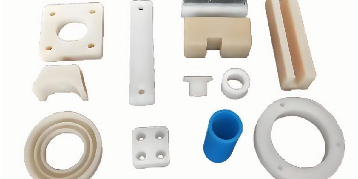
Figure 1-1: Key components of a standard injection mold assembly, demonstrating essential design for injection molding principles
Part Preparation & Cavity Creation
塑件图处理 (Plastic Part Drawing Preparation)
The first critical step in design for injection molding is properly preparing the plastic part drawing for mold integration:
- Add shrinkage dimensions to the plastic part drawing. The specific shrinkage rate depends on the plastic material and part geometry, a key consideration in design for injection molding.
- Create a mirrored version of the dimensionally adjusted part drawing.
- Incorporate this mirrored, dimensionally adjusted drawing into the mold design as the cavity layout.
基准标注 (Datums and Reference Points)
Proper datum identification is fundamental to precision in design for injection molding. Mold drawings must clearly indicate both mold datums and part datums, along with their distances from the mold center.
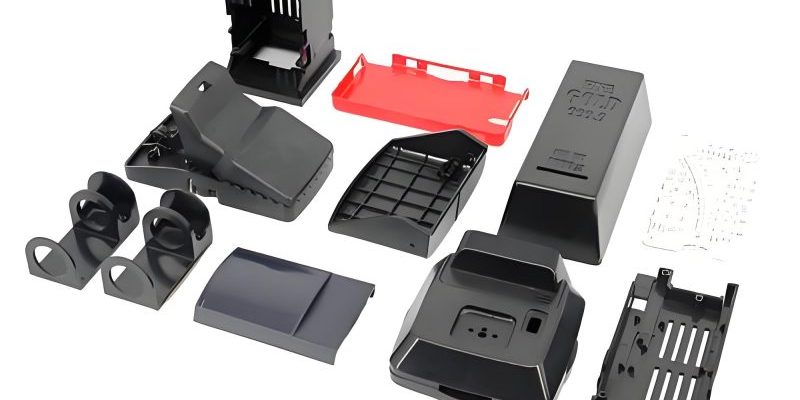
Figure 1-11: Properly标注的模具基准和塑件基准 (marked mold datums and part datums) in a mold design
The datums serve as the reference points for all critical dimensions in the mold, ensuring consistency across production runs and facilitating accurate assembly. This attention to reference points is a hallmark of sophisticated design for injection molding practices.
Mold Dimension Specifications
Determining appropriate mold dimensions based on part size is a critical aspect of design for injection molding. These dimensions ensure proper function, cooling, and durability of the mold during production.
| Mold Type | Dimension | Standard Range | With Slides |
|---|---|---|---|
| Two-plate mold | A | 45~70mm | 100mm |
| Three-plate mold | A | 75~100mm | 150mm |
| Part <150mm×150mm | B | 15~25mm | |
| D | 25~50mm | ||
| Part >150mm×150mm | B | 25~50mm | |
Additional Dimension Guidelines
- Dimension C: For parts smaller than 150mm×150mm, C should be less than 30mm.
- Dimension D: Generally calculated as C + (20~40mm), a critical relationship in design for injection molding that ensures proper material flow and cooling.
- Dimension E: Moving platen should generally be larger than 2D; fixed platen should be slightly smaller than 2D.
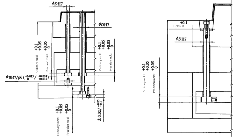
Figure 1-12: Mold dimension reference showing the relationship between critical dimensions in design for injection molding
Shrinkage Rate Specifications
One of the most critical factors in design for injection molding is accurately accounting for material shrinkage. Proper calculation and application of shrinkage rates ensure that the final part dimensions meet specifications after cooling.
确认塑料及收缩率 (Plastic Material and Shrinkage Confirmation)
It is essential to verify that the correct plastic material and corresponding shrinkage rates are used in the mold design. A key principle in design for injection molding is recognizing that some plastic parts may exhibit different shrinkage rates in various directions.
Example: POM Material Shrinkage Rates
- Core: 2.2%
- Cavity: 1.8%
- Parting surface and center distance: 2.0%
This directional variation in shrinkage highlights why material-specific analysis is fundamental to design for injection molding. Using incorrect shrinkage rates can result in parts that are out of tolerance, require excessive post-processing, or fail to assemble properly.
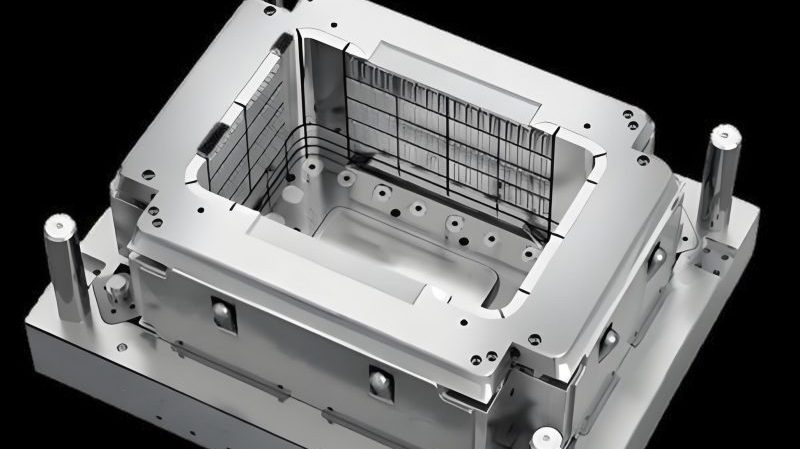
Figure 1-13: Shrinkage rates must be determined based on plastic material and dimensional characteristics, a key principle in design for injection molding
Mold Base and Component Specifications
基准角标示 (Reference Corner Marking)
Both the mold base and insert reference corners must be clearly marked, and their orientations must be consistent throughout the design. This standardization supports accurate assembly and maintenance, key aspects of robust design for injection molding.
Consistent reference corner marking ensures that all components align correctly during mold assembly, reducing setup time and minimizing errors during production.
斜度要求 (Draft Angle Requirements)
For shut-off and擦穿面 (wiping surfaces), a minimum draft angle of 3° must be maintained. This helps prevent damage to the mold surfaces during operation and facilitates proper part release, both essential considerations in design for injection molding.
吊环螺孔规格 (Lifting Eye Specifications)
The specifications and dimensions of mold base lifting eye bolt holes must be clearly indicated in the design. For mold bases wider than 450mm, lifting eye bolt holes should be added to all four sides of both A and B plates.
Proper lifting eye placement is not only a safety consideration but also ensures that the mold can be handled without distortion, preserving dimensional accuracy – an important aspect of design for injection molding that impacts long-term performance.
螺钉标注 (Screw Specifications)
Screw length, thread depth, and specifications must be clearly indicated on the mold drawings, along with a sequential numbering system (e.g., S1, S2, etc.).
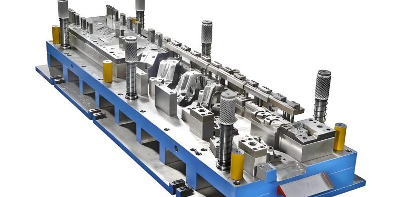
Figure 1-14: Proper screw and threaded hole标注 (marking) in mold design documentation
Cooling System Specifications
An effective cooling system is vital for efficient production and part quality in injection molding. Proper cooling design is therefore a cornerstone of design for injection molding, directly impacting cycle time, part warpage, and dimensional stability.
冷却水孔设计 (Cooling Channel Layout)
The flow path of cooling channels must be clearly indicated in the mold design. Optimal spacing between cooling channels is 50mm, with a distance of 15~20mm from the parting surface or plastic part being ideal.
Figure 1-15: Cooling channel positioning relative to part surfaces in effective design for injection molding
Special attention must be paid to ensure that cooling channel O-rings do not interfere with ejector pins, screws, lifters, or other mold components. This integration of systems is a key aspect of sophisticated design for injection molding.
水孔标注 (Cooling Channel Identification)
All cooling channels must be numbered, with their diameters and the thread specifications of water connections clearly marked. Examples include: 1#IN, 1#OUT, 1/8PT, 1/4PT, etc.
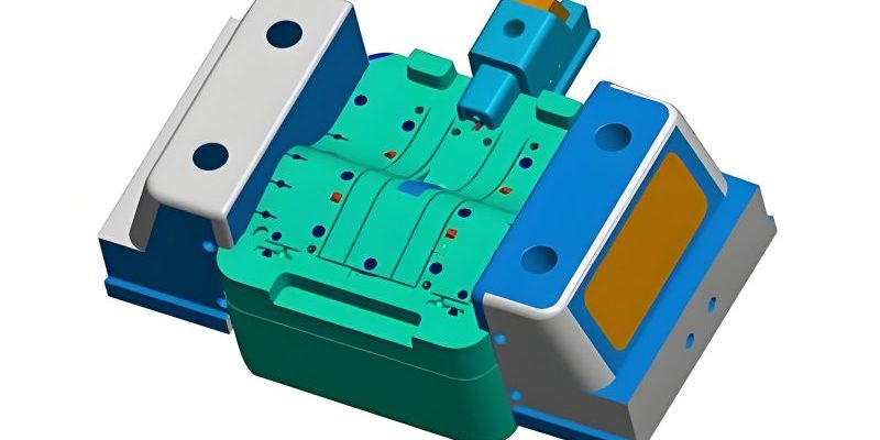
Figure 1-16: Proper cooling channel identification in a mold design drawing
Cooling System Performance Metrics
The following chart illustrates the relationship between cooling channel distance from part surfaces and typical cycle time reductions, demonstrating why this aspect is critical in design for injection molding:
Ejection System Standards
The ejection system is responsible for safely and efficiently removing parts from the mold cavity after each cycle. Proper design of this system is essential for maintaining part quality and mold longevity, making it a critical aspect of design for injection molding.
推杆设计 (Ejector Pin Specifications)
- Ejector pins, sleeves, and flat ejectors should generally be positioned at least 2.0mm away from cavity edges (such as ribs).
- Ejector pin arrangement should ensure balanced ejection to prevent part deformation during removal, a key consideration in design for injection molding.
- The maximum diameter of ejector pins should not exceed 12mm.
- Non-standard ejector pins and sleeves should be avoided (e.g., a 6.03mm×43.02mm boss sleeve should be ordered as 6mm×43mm), unless specifically required by the customer.
滑块及斜顶行程 (Slide and Lifter Stroke)
The stroke of slides and lifters must be clearly indicated in the mold design, and their adequacy verified. Proper stroke calculation ensures complete part release without interference, an important element of reliable design for injection molding.
Part Feature Representation
塑件字体表示 (Text Features on Plastic Parts)
The content, position, size, and depth (raised or recessed) of any text on the plastic part must be clearly indicated in the insert drawings. This level of detail ensures that text features are reproduced accurately, maintaining brand identity and functional information – an often-overlooked aspect of design for injection molding that directly impacts part usability.
线型与颜色规范 (Line Types and Color Standards)
In mold design DWG files, the same line types must be represented by the same colors. Consistent line formatting enhances drawing clarity and reduces errors during mold fabrication, supporting efficient design for injection molding workflows:
- Center lines: Color 1 (red) on "center" layer
- Hidden lines: Color 4 (light green) on "unsee" layer
- Visible lines: Color 7 (white) on "continuous" layer
- Cooling channels: Color 5 (green) on "pipe" layer
- Dimension lines: Color 3 (blue) with text in color 7 (white) on "dim" layer
- Hatching: Color 8 (gray) on "hatch" layer
- Insert lines: Color 6 (purple) on "imag" layer
This standardized approach to line formatting ensures that all stakeholders can quickly interpret critical information in the drawings, supporting effective communication throughout the design and manufacturing process – a key component of successful design for injection molding implementation.
Technical Requirements Documentation
Clear technical requirements ensure that all mold components are manufactured to the correct specifications. Proper documentation of these requirements is essential for quality control and consistency in design for injection molding.
技术要求内容及顺序 (Content and Order of Technical Requirements)
Required sections in order:
- Material
- Quantity
- Heat treatment
- Cavity identification
- Edge chamfers (on non-cavity surfaces)
- Additional notes
General requirements:
- Technical requirements must be placed in the lower left corner of the drawing, filled in from top to bottom.
- Technical requirements must include at least items a), b), and e) from the list above. Items c), d), and f) may be included as needed.
- When a part is modified from a standard component, the material section should note "STD" or "XX specification of XXXX (standard part code)".
技术要求示例 (Examples of Technical Requirements)
Example 1:
Technical requirements:
- Material: S50C
- Quantity: 1 piece
- Edge chamfer 1×45°
Example 2:
Technical requirements:
- Material: NAK80
- Quantity: 1 piece
- Heat treatment: Nitrided layer depth 0.15mm, 68~70HRC
- "--------" indicates cavity surface, data from 3D model
- Non-molding surface edges chamfer 1×45°
Example 3:
Technical requirements:
- Material: O1
- Quantity: 2 pieces
- Heat treatment: Quenched and tempered twice 52~56HRC
- "--------" indicates cavity surface, data from 3D model
- Non-molding surface edges chamfer 1×45°
Example 4:
Technical requirements:
- Material: 8407
- Quantity: 1 piece
- Heat treatment: Quenched and tempered twice, 50~51HRC
- Edge chamfer: 1×45°
图层管理 (Layer Management)
Different layers should be created in the CAD file to organize different types of part lines. This structured approach enhances drawing clarity and editability, supporting efficient design for injection molding workflows:
- Dimension lines on "dim" layer
- Cooling channel lines on "cool" layer
- Ejector pin outlines on "inject" layer
- Insert components on "insert" layer
- Mold base and structural components on "mould" layer
Consistent layer management enables efficient updates and modifications to the design, reducing the risk of errors when changes are required – a valuable practice in agile design for injection molding environments.
Elevate Your Mold Design Process
Adhering to these mold design standards ensures that your injection molding process will produce high-quality parts efficiently and consistently. By implementing these principles of design for injection molding, manufacturers can reduce production issues, minimize waste, and improve overall part quality.
Continuous improvement in mold design practices, combined with a deep understanding of material properties and manufacturing processes, is key to success in today's competitive manufacturing landscape.
Learn more